Saturday, 13 December 2014

Tamiya 1/32 Spitfire XVIe - Final Reveal

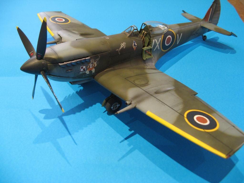
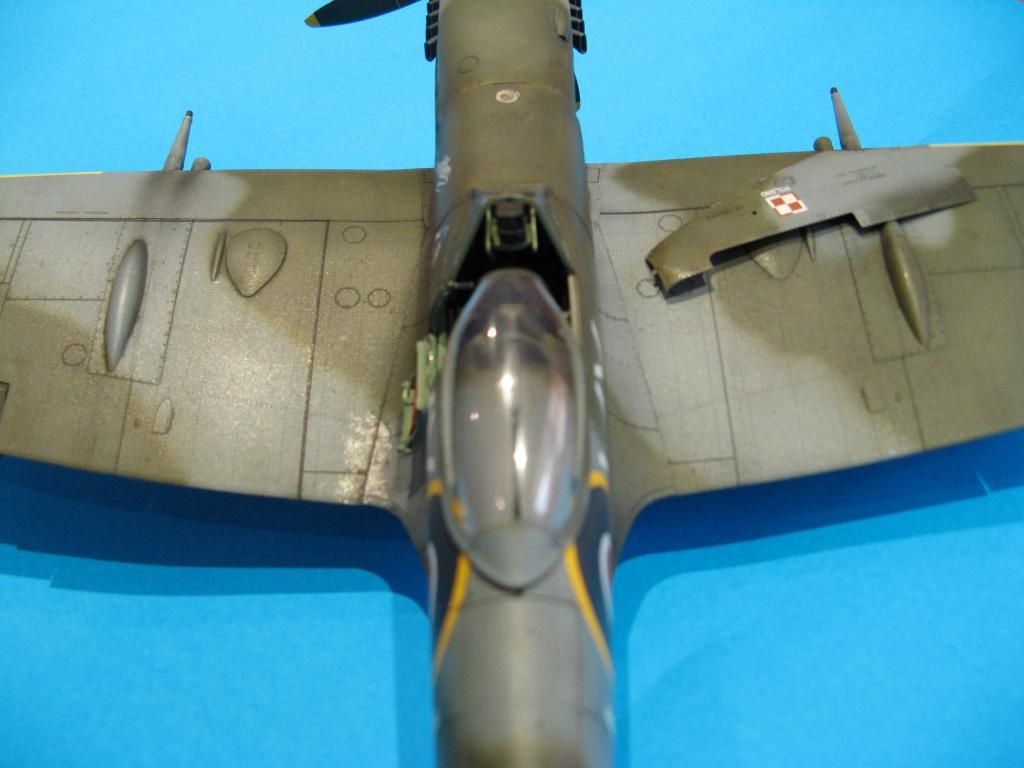
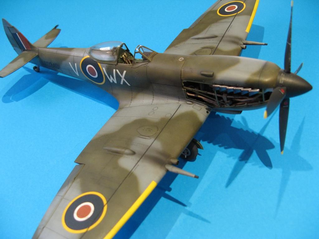
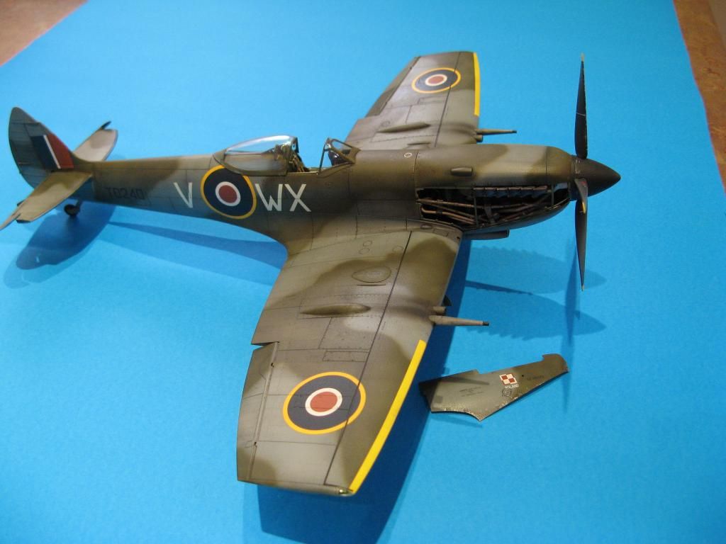
Spitfire XVIe Final Reveal

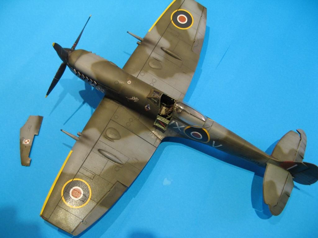
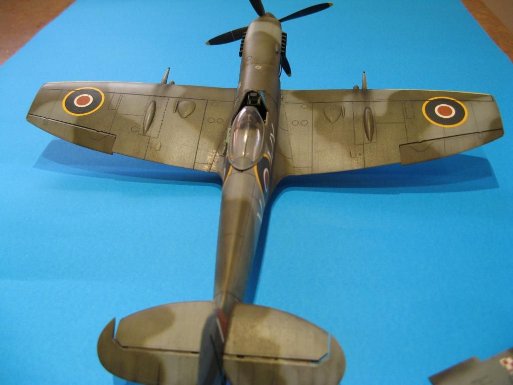
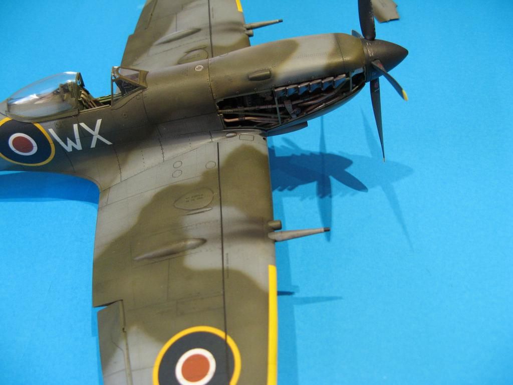
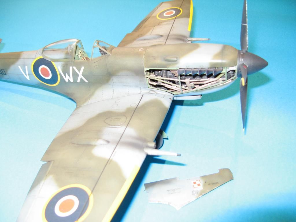
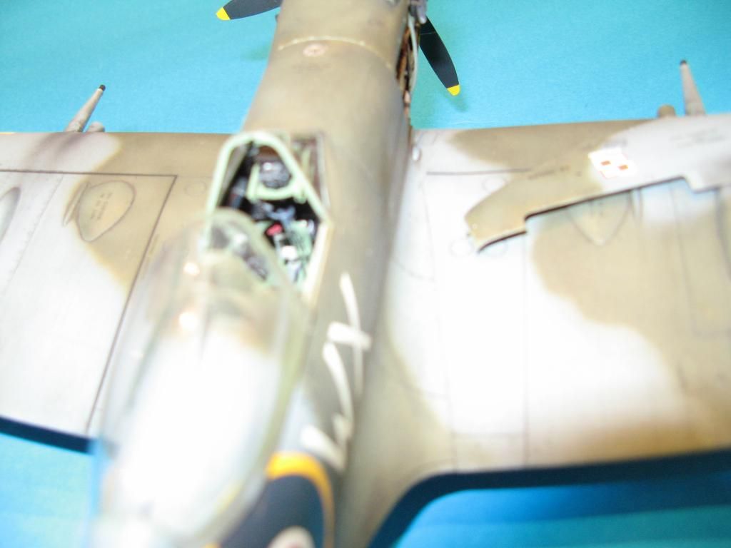
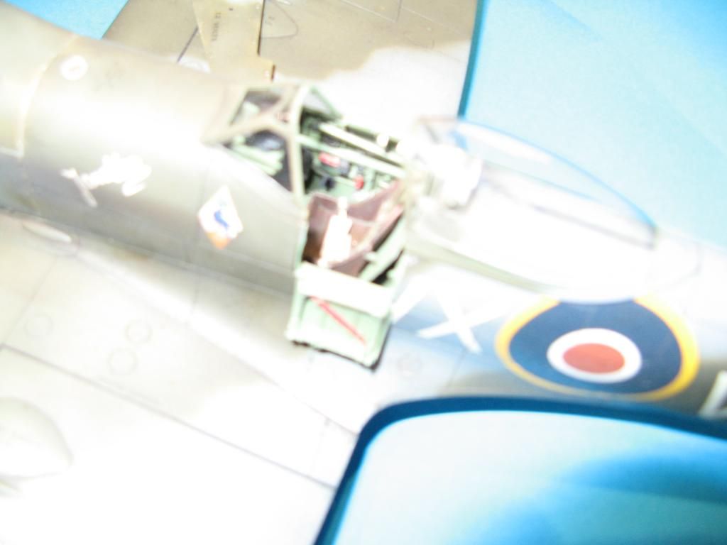
Here are the pictures of my completed 1/32 Spitfire XVIe.  The fit of the Tamiya kit is great but my modification of the engine did not help matters.  Putting in the spark plug wiring pushed a few bits ever so slightly out of alignment making the fit of the cowlings somewhat snug.  The Eduard photo etch added a lot to the cockpit.  The Brass gun barrels from master were a bit problematic getting them to fit.  They're a bit too tight.  I am happy with the result.  it certainly looks like a Spitfire.  I just wish I was small enough to jump in it and fly it around.

Here's a few with the flash on.

Saturday, 6 December 2014

Tamiya 1/32 Spitfire Mk XVIe - Part 5

Back to part 4

Getting the Wings On

Attaching wings to the fuselage is something that always worries me.  There's usually a risk of getting a nasty wing joint which requires filler and sanding in an awkward spot.  With this kit however that was not a problem at all.  The fit was wonderful.

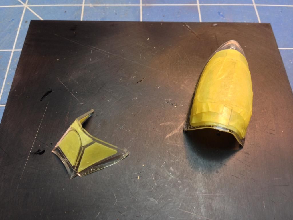
After the glue had dried I carefully inspected the join lines and applied a little filler in the odd spot.  The good thing about using the Big Ed set on this kit is that I had masks for inside and outside of the canopy.

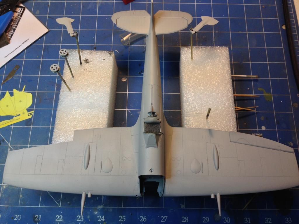
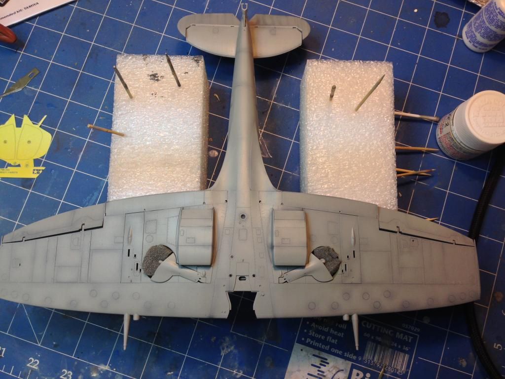
The canopy was spayed with the interior green XF-71 colour and the front part was glued in place. So, with joins checked and canopy done, it was time to prime.

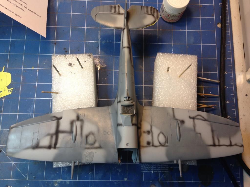
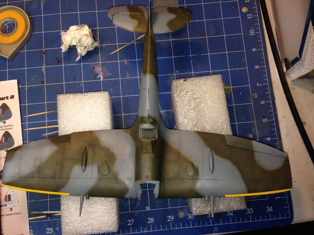
The primer was left to dry for a few days.  Afterwards the panel lines were preshaded in black and painting of the camo commenced.  The lower colour is Tamiya XF-??.   After a good covering this was lightened with some white paint, thinned and used to mottle the centre of panels.

A similar approach was used on the two upper camouflage colours.

The entire model was then given a gloss coat and left to dry for a few days.

Next time we get the decals on.

On to part 6.

Saturday, 1 November 2014

Tamiya 1/32 Spitfire Mk XVIe - Part 4

Back to part 3

Getting Your Wings Clipped

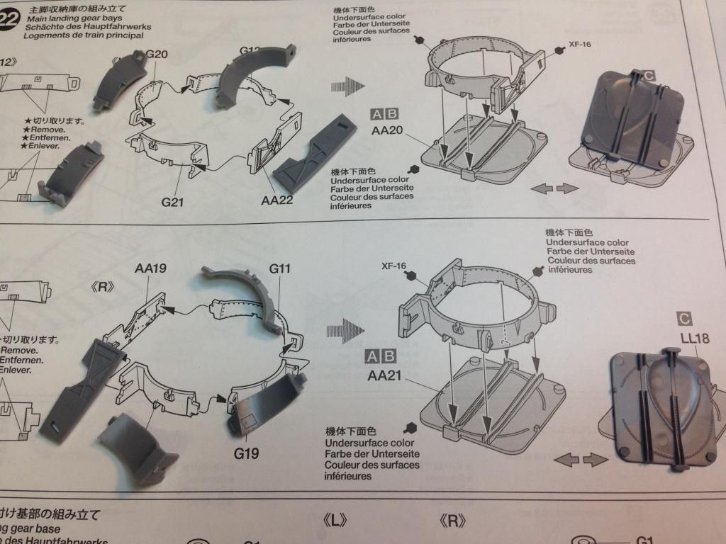
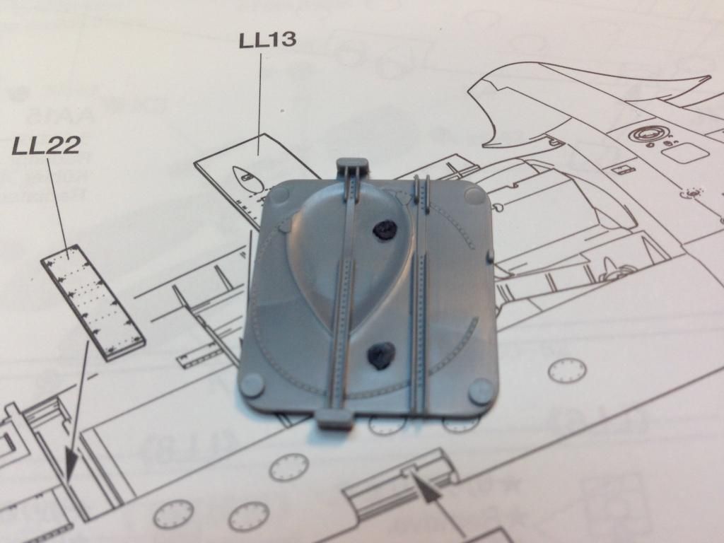
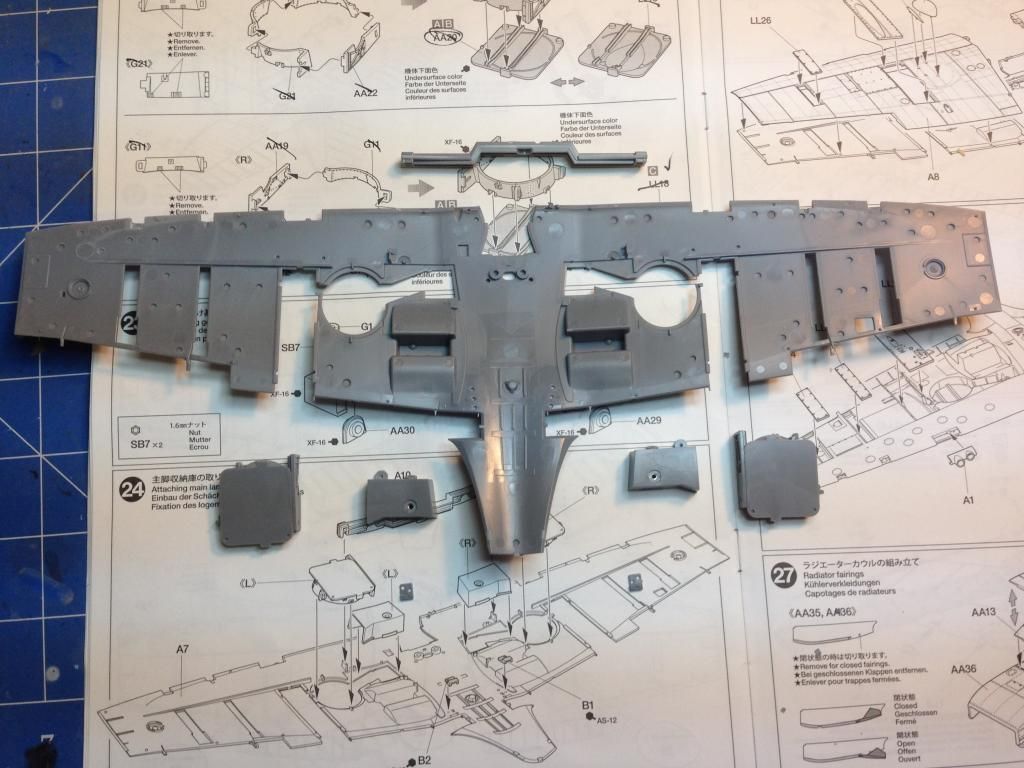
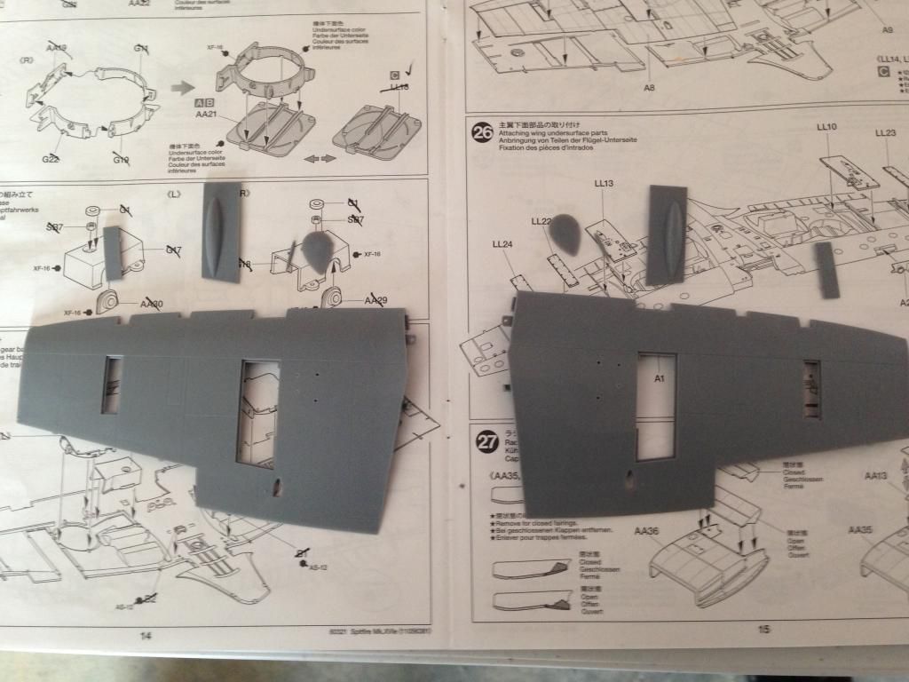
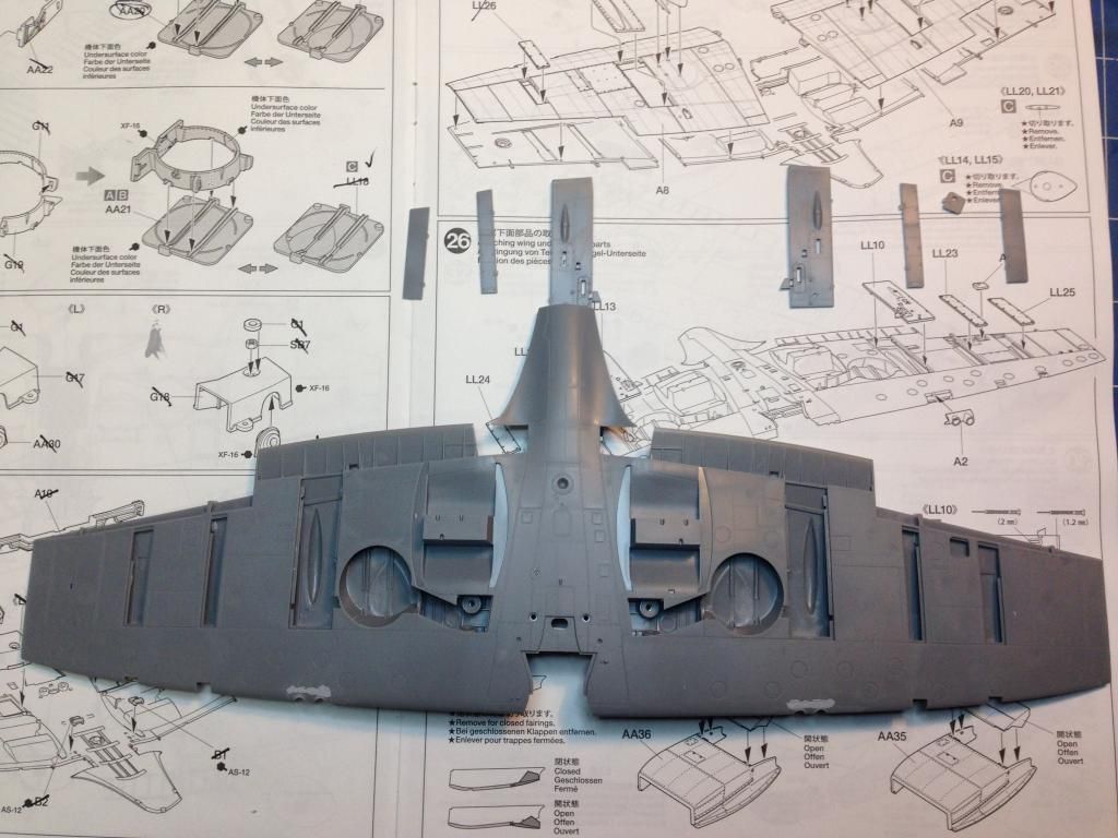
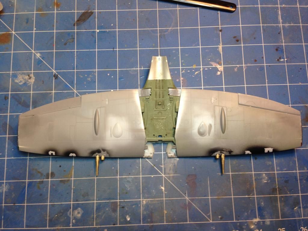
Construction of the wings starts with the undercarriage bays.  These are a fairly complicated arrangement with this section of the wheel bays having five parts per wing.  The fit of these is excellent.

Again, and surprising for a Tamiya kit, is the presence of ejector pin marks where they would be visible.  Nothing that a few swipes of a sanding stick can't take care of though.  You do need to be careful doing this in case you damage some of the detail.

The inner part of the wheel wells comprise another four parts per wing.  One of these is a tiny nut that will secure the lading gear once it's attached.

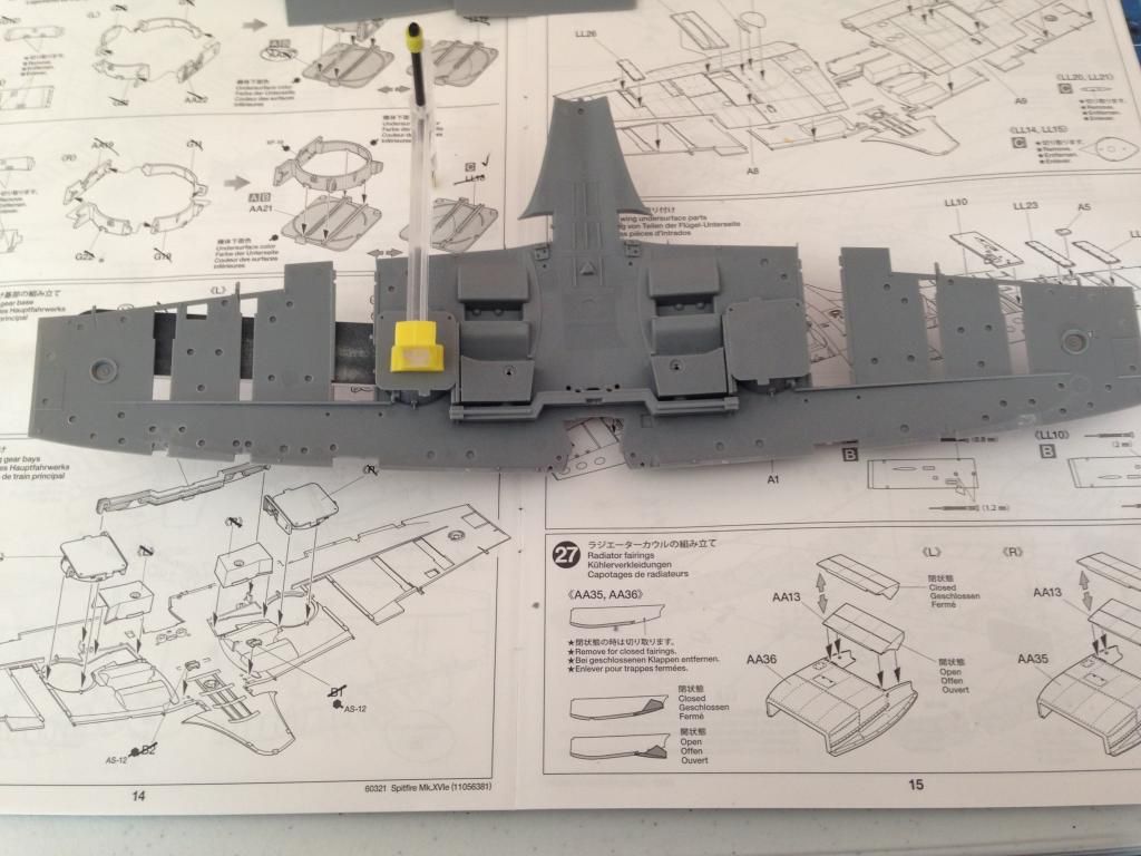
The wings themselves are quite flimsy at this stage.  In order to add strength a small wing spar is supplied.

The upper wing sections have covers for the weapons and the version that I am building has some extra bumps on the wing.  Care needs to be taken gluing these as the capillary action of the cement can zip around and easily get under your finger where you may be holding the wing leaving a nasty fingerprint melted into the plastic.  So, watch where you hold it, and glue from the underside.

Once the upper surfaces of the wings were dry, the lower wing surface can be fitted.  Again there are a few panels which need to be glued with care.  The worst fitting piece that I have so far encountered on this kit would the weapons fairing on the leading edge.  These needed a bit of Mr Surfacer 500 to ensure a gap free join.  They were also drilled out to accept the turned brass gun barrels which will be fit later.

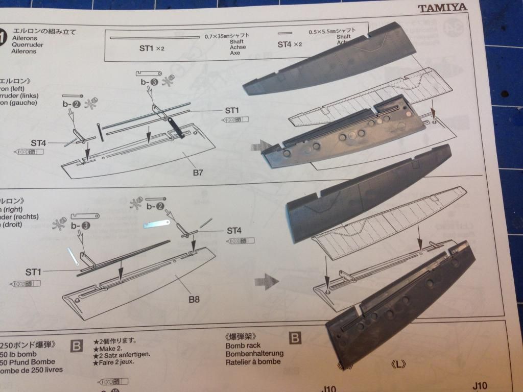
The ailerons were also assembled.  These will be a push fit later allowing them to move.

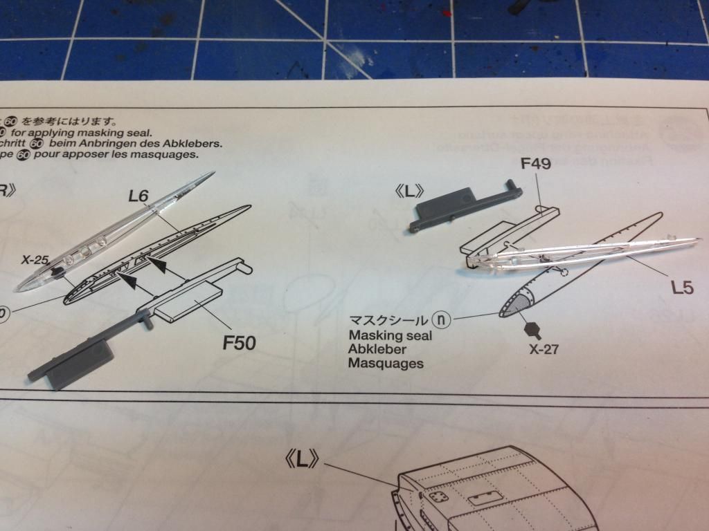
The wingtips are made out of clear plastic.  This allows for painting of the navigation lights from the inside


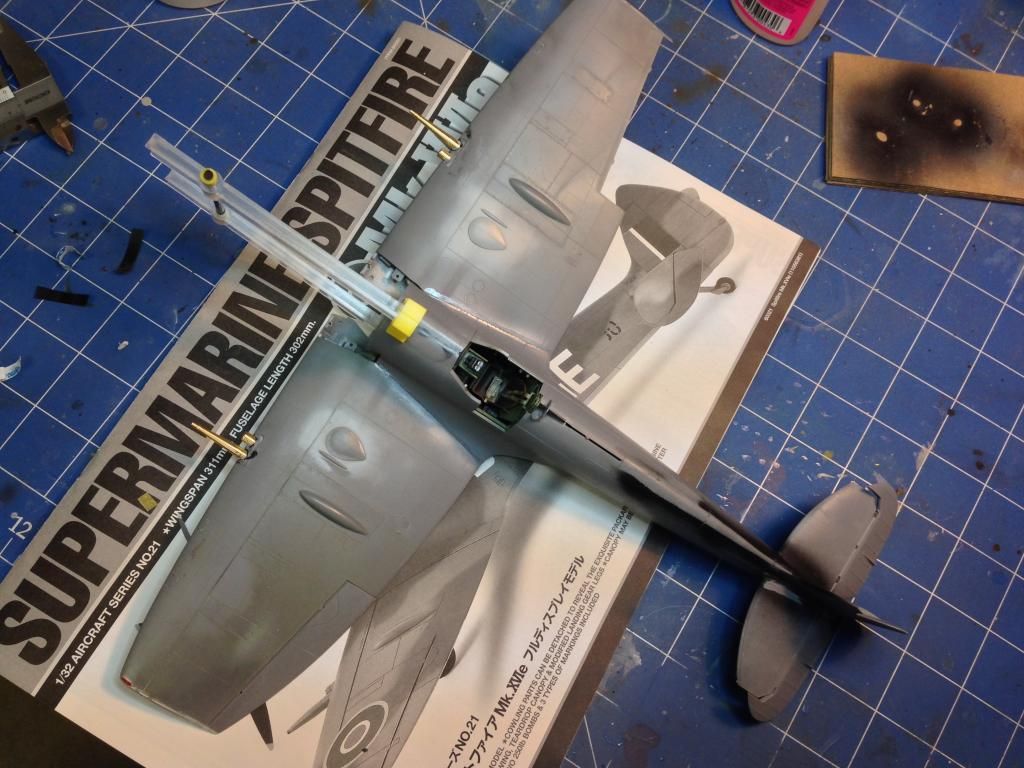
The wings were eventually completed and the brass gun barrels were fitted.  These were quite difficult as the fit was very tight.  In the end I put them in loose and adjusted them until I was happy.  I then used some thin CA glue around the join to the wing.  Capillary action sucked the CA into the tight join but there was still a bit of a visible join line.  Once the CA had dried I painted some Mr Surfacer 500 into the join and I used some lacquer thinners on a cotton bud to remove the excess after it had dried.

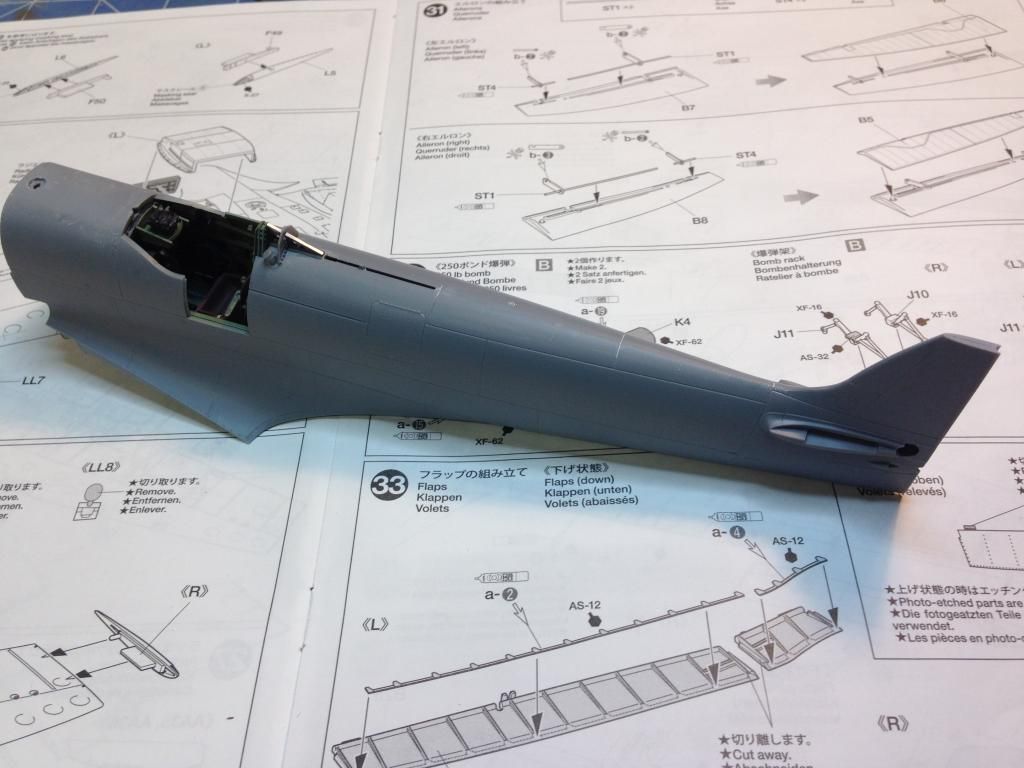
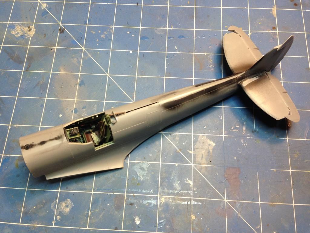
The fuselage was also glued together.  This was a great fit.

The tailplane was fitted and a bit of black paint was sprayed onto the fuselage join lines to ensure that they would look good when painted.

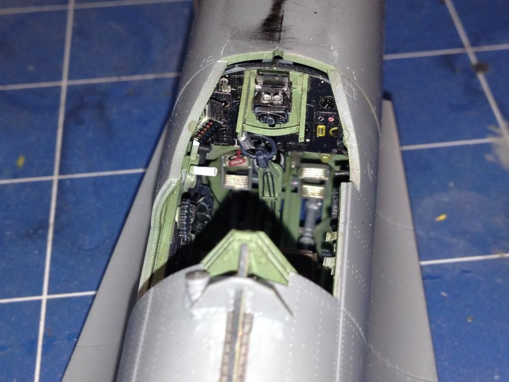
I'm pretty happy with the way the cockpit turned out.  It looks like you could jump in there and fly it.

Next time I'll get the wings onto the fuselage and get everything ready for a primer coat.

Onto part 5.

Saturday, 11 October 2014

Tamiya 1/32 Spitfire Mk XVIe - Part 3

Back to part 2

The Magic of a Merlin

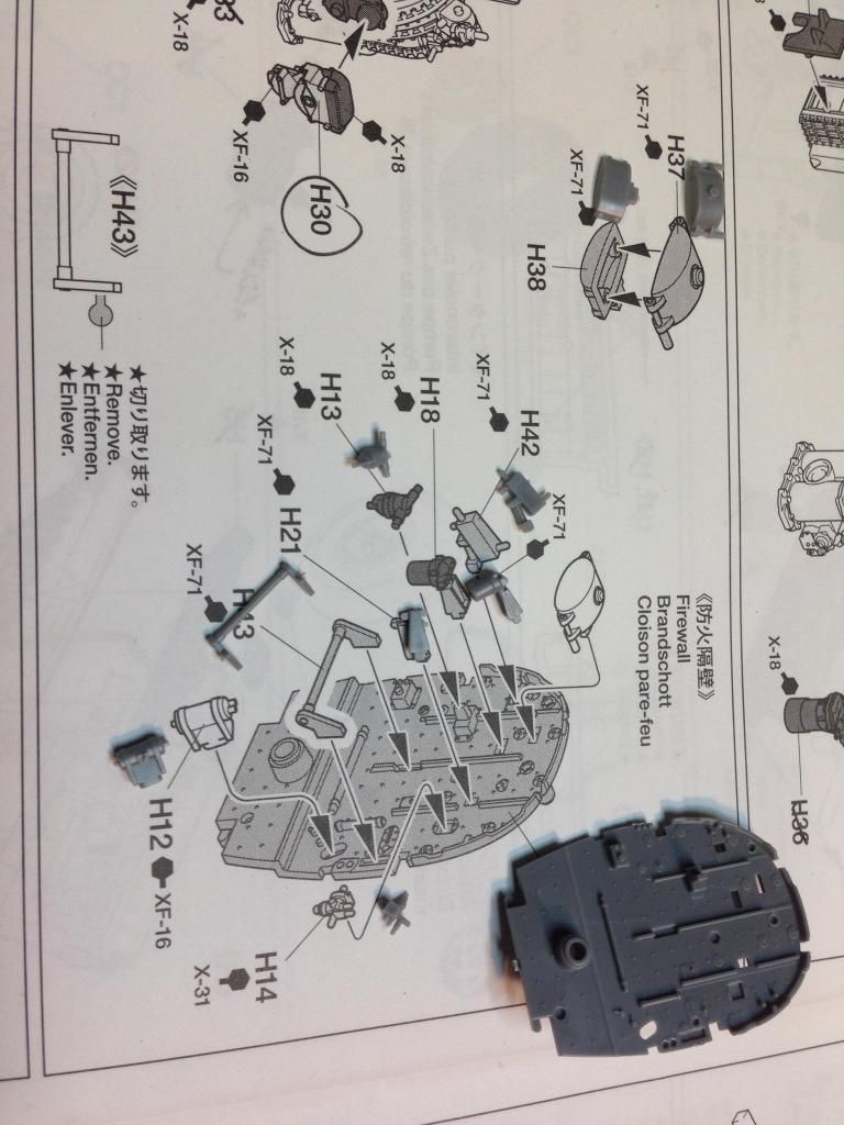
With most of the main engine assembly completed I moved onto the firewall.
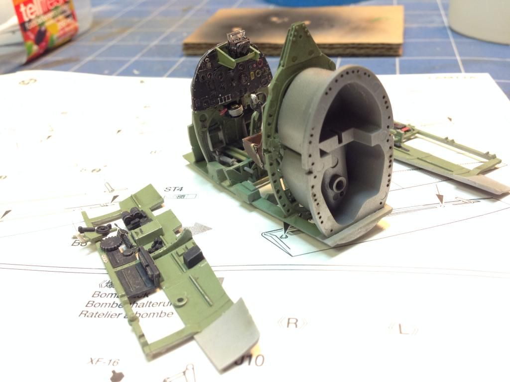
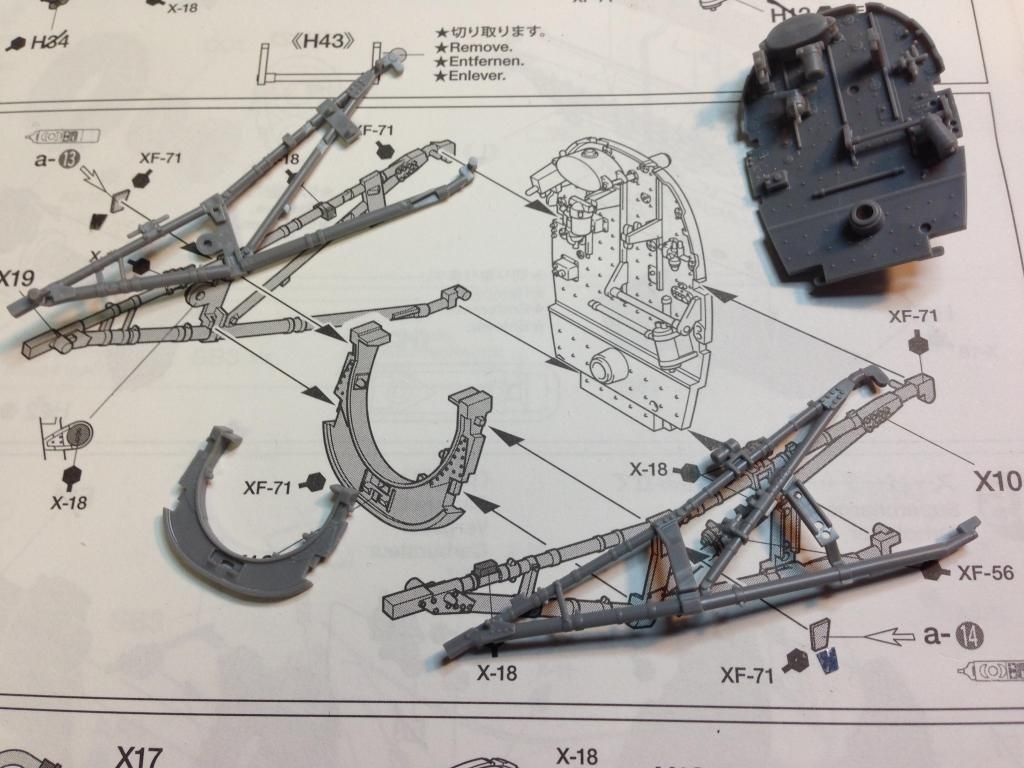
There quite a bit of detail on this.  Once assembled it was mated with the engine bearers.

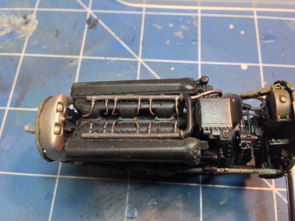
 There was a bit of Eduard photoetch put onto the U-shaped bit that goes between the engine bearers.  A number of pipes and whatsits were added and then the entire assembly was painted and brought together.  The view from the top shows how the scratch built wiring harness turned out.

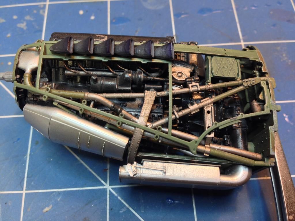
The last bit of the engine involved assembling and painting the cowling frames and exhausts and bringing this together with the rest of the engine.  The exhausts were painted using Mr Metal Colour Dark Iron which was polished and then sealed with future.  The final touch involved spraying the ends of the exhausts with a little Alclad II hotmetal violet to give the impression of heat bloom.  the whole thing was then given a wash of very heavily thinned Vallejo 71.041 Tank Brown then sealed with future.  Afterwards a wash of AK Interactive engine grime was applied and, once dry, the whole thing was given a flat coat.

On to the Cockpit

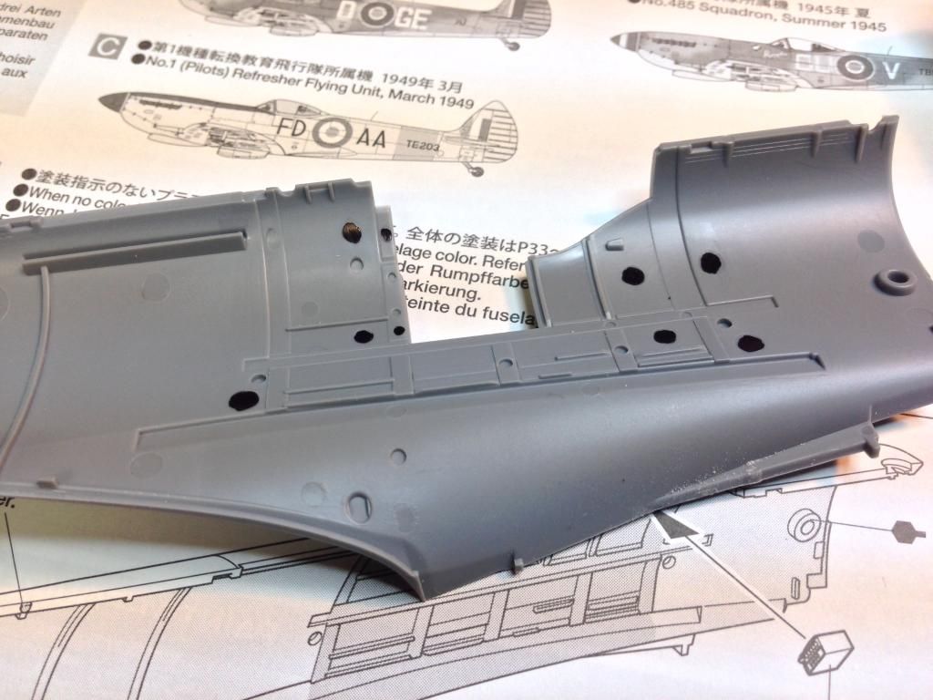
It surprised me how many ejector pin marks were on the fuselage halves around the cockpit area.  I counted nine which gave me concern (marked with black marker) but you can see others nearby was well.

Tamiya are renowned for their precision engineering so my suspicion was that these would not be seen.  However, I decided to remove some of the more accessible ones just in case.

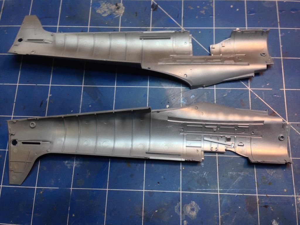
I wanted the cockpit to look used.  After adding a few bits of photoetch, the first part of this process was spraying the interior with Alclad II Duraluminum.

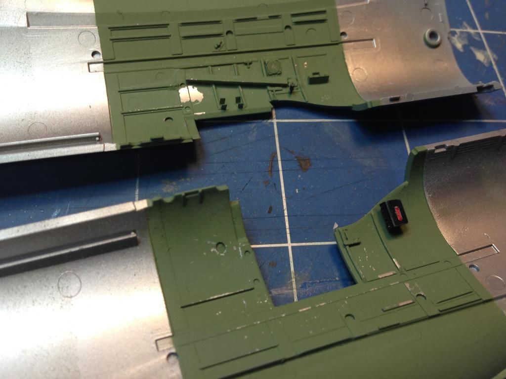
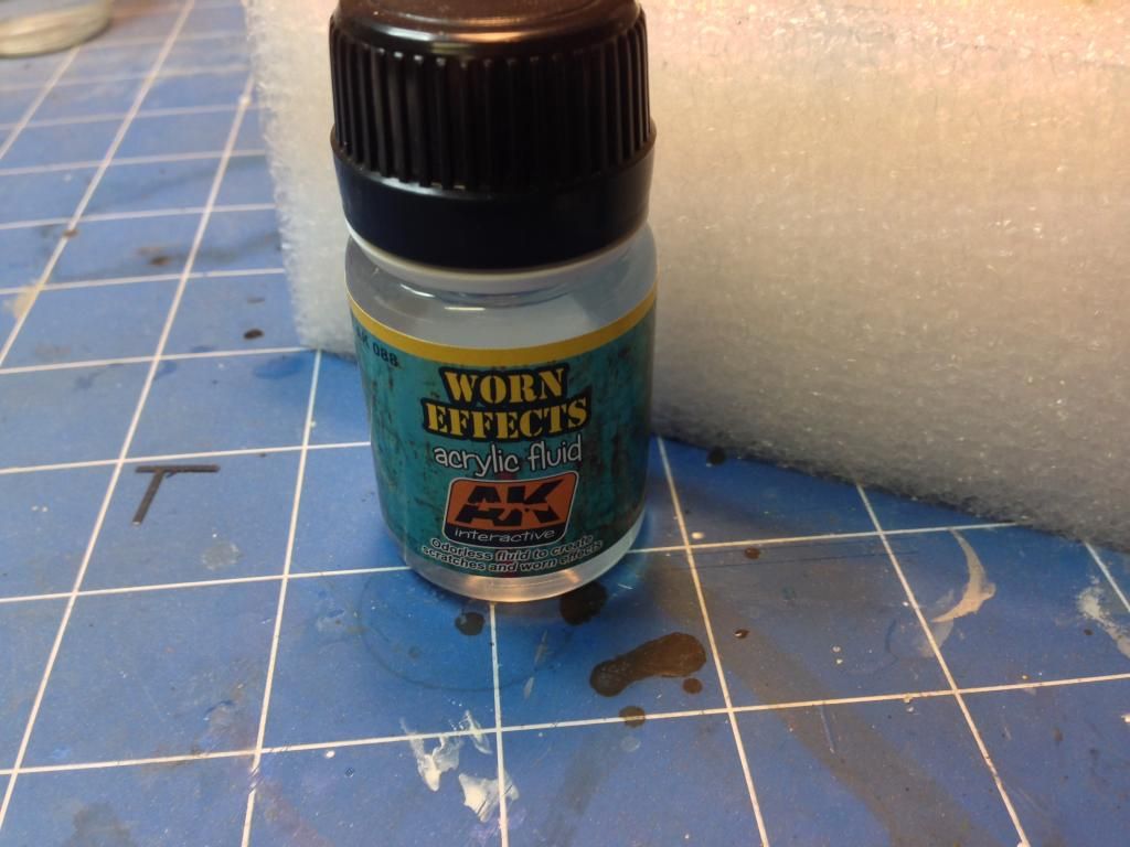
The interior forward and aft of the cockpit was then masked and AK Interactive worn effects chipping was sprayed onto the cockpit sections.  This was followed up with a coat of Tamiya XF-71 Interior Green.  After this was dry, water was used to humidify the worn effects resulting in the (mostly) light chipping seen in the image below.

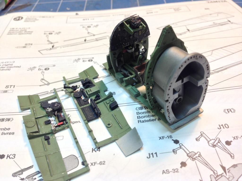
Unfortunately I didn't take too many pictures of the cockpit assembly but the process involved building and painting sub-assemblies. AK Interactive worn effects was used for chipping and AK Interactive interior wash was used to give the cockpit a grimy appearance.  The colour is mainly Tamiya XF-71 Interior green with details picked out by hand in black and other colours.  The Eduard interior set was used to add details and the Eduard cockpit placards set was used to make it look a bit more real.  A prismatic silver colour pencil was used to enhance some of the chipping with smaller scratches.

I'm going to leave this update here.  Next time we get the fuselage together and get on with the wings.

On to part 4

Saturday, 6 September 2014

Tamiya 1/32 Spitfire Mk XVIe - Part 2

Back to part 1

And We're Off...

I'm building this model at the same time as a friend of mine is building his.  He's already built the engine so that's where I decided to start as well.  The Spitfire XVIe had a Packard built Merlin 266 engine. Finding references for this specific engine did prove a challenge but eventually I did find some after trawling through images on Google.  The Tamiya engine is quite amazing out of the box but there are a few places where more detail can be added.

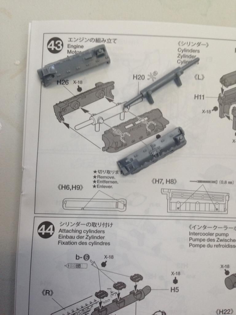
Construction started with the crankcase assembly.  For a while I was puzzled as to why part H20 was not glued into each side of the crankcase.  I admit that I considered gluing it, but after some consideration I decided that the good folks at Tamiya know what they're doing so I didn't glue it in the end.  Later in the assembly of the engine we'll find out why it is not glued - well my theory anyway.

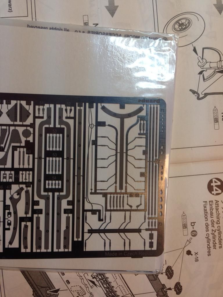
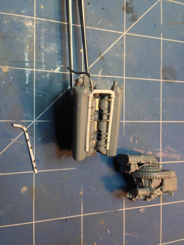
The Eduard exterior detail set comes with a wiring harness for the spark plugs.  I didn't like the look of it for two reasons.  Firstly, on the Packard Merlin 266 the harness which sits on the top is actually in two parts not one as the Eduard photoetch would suggest.  The second reason is being photoetch it's flat.


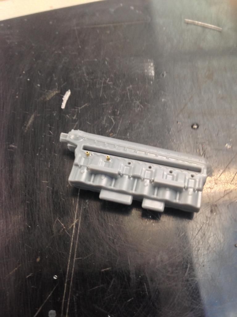
The solution was to build my own. I started by using 0.6mm brass tubing to replicate the spark plugs.

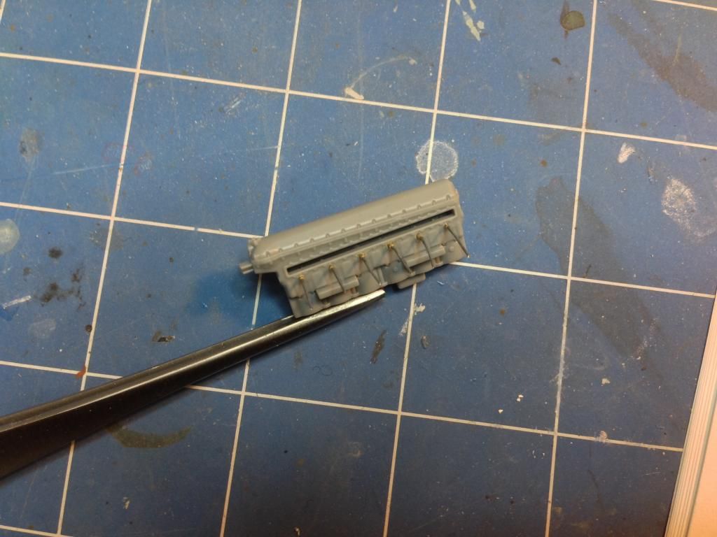
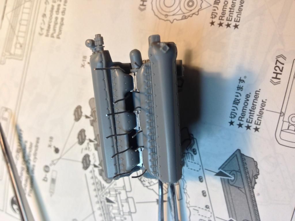
This was then given leads made from 0.4mm lead wire.

Then the cylinder blocks were cemented to the crankcase.  The sparkplug leads were fed carefully around the manifold.

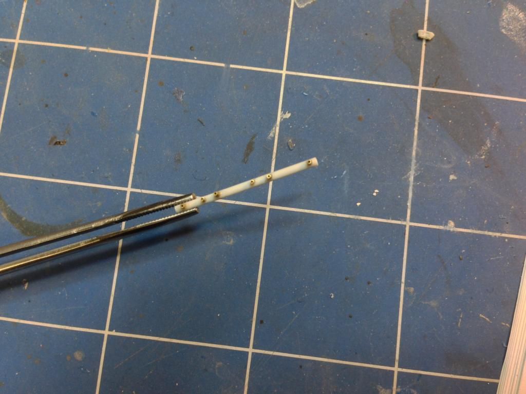
These leads needed a harness to be wired into so I had to scratch make them as well.  The main parts of the harnesses were made of 1.2mm plastic rod which was carefully drilled to accept some 0.6mm brass tubing.

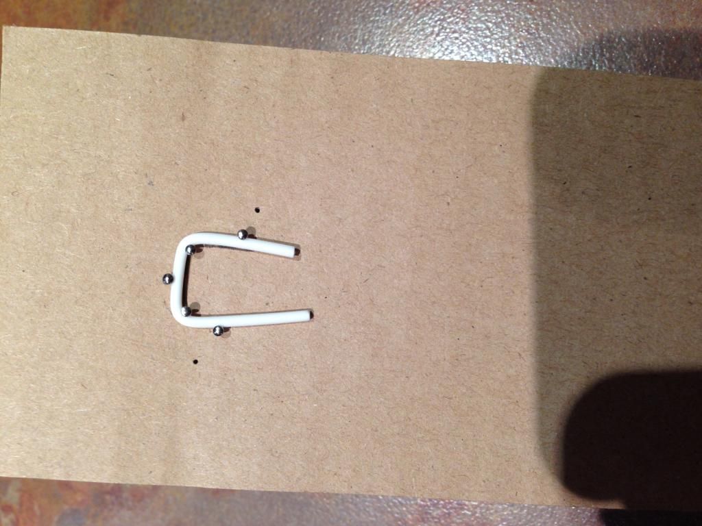
The upper wiring harnesses are connected by a conduit that is thicker than the harnesses.  This was made out of 1.6mm plastic rod but it needed to be the correct shape.  I started with a small piece of rod and held it in place with a few pins on a piece of cardboard.  I then heated it with a hairdryer set on hot and carefully bent the plastic until it was the shape I needed and then pinned it so it stayed in that shape.  It was then allowed to cool.  My theory was it would stay in that shape once it cooled and that was sort of true.

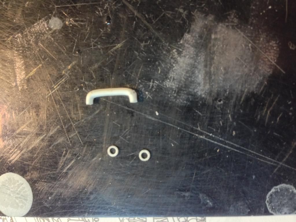
Once this was the right shape I cut it to size and made two collars for it using the Waldron punch set.

I could then assemble the harness and wire it into the sparkplug leads.  Here's the assembled harness on the top after wiring it in.  Next to the engine is one of the side harnesses and the supercharger assembly.  Extra plumbing was added to that as well.  Notice that the pipes leading out of the side harnesses face forward and one of then is slightly offset to clear the intercooler pump.

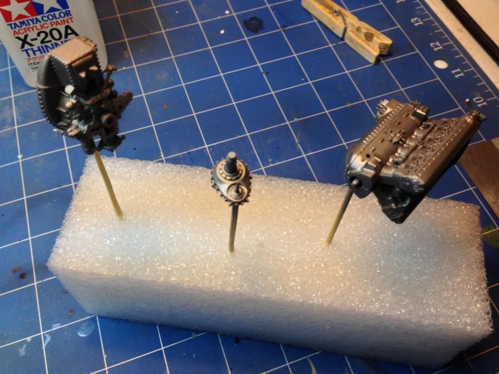
The engine assemblies were primed and then given a coat of Citadel Boltgun metal.  This would give a metallic undercoat which would show through chips on the engine.

I used AK Interactive's worn effects to create some chipping effects on the engine.

In the next update the engine will be completed and work will commence on the cockpit.

On to part 3.