Saturday, 12 July 2014

1/48 Hobby Boss Ta 152 C-0 - Part 4

Back to part 3

Hello again.  It's been a long time since I last updated this but my build of this aircraft continues with some work on the propeller and spinner.  I also get the wings on.

You Spin Me Right Round

I mentioned right at the beginning that I didn't think that the spinner or prop blades were right in this kit.  The aircraft I am building had a spinner design seen on the Ta152 H prototypes and on some Fw190 D prototypes.  You can see in the photo below that a defining feature of this spinner is the large hole in the end.
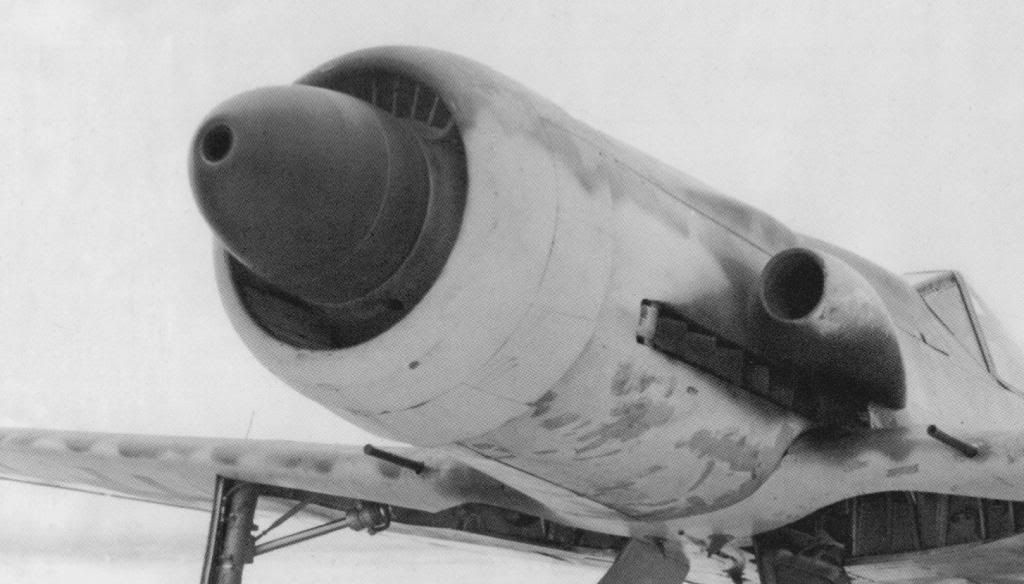
This feature is missing from the kit spinner.

In an attempt to rectify this I bought the Quickboost spinner and propeller replacements.  It was not much better than the kit so I needed to source a more correct spinner.  I think I got close with the Engines and Things conversion set for the Fw 190 D-11.  The three choices are shown in the image below.  On the left is the Engines and Thing spinner, in the middle is the kit spinner and on the right is the Quickboost spinner.  You can see they're all quite different.
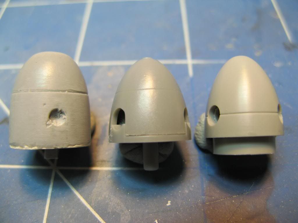
I resolved to start with the Engines and Things spinner and modify it to match my references.  Frankly its a pretty awful casting so there will be a fair bit of work to get it to the state that I want.

Similarly the propeller blades are the wrong shape.  The actual aircraft has large paddle shaped props as shown below.

None of the alternatives I had to hand were quite right.  In the picture below from left to right we have the Engines and Things prop, the kit prop, the Quickboost prop and some I had in my spares box from the Dragon Ta 152H.  They are all different shapes but the closest is the one from the Dragon kit.
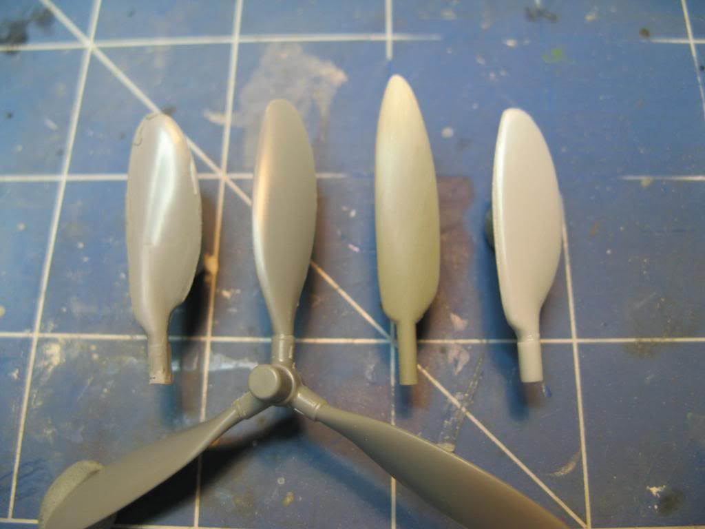
I opted to use the Dragon one as a basis for making my own.  First I got measurements of the correct length from some plans I have in one of my references.  This showed the Dragon blade to be too short by about 1mm.  The trailing edge of the Dragon blade is also wrong where it begins to flare out.  I traced the Dragon blade on paper using a pencil and made corrections to the drawing using a fine marker.  I then used the corrected drawing as a template to correct the shape.  I started by cutting the trailing edge off the Dragon blade and attached plasticard using plenty of super glue.
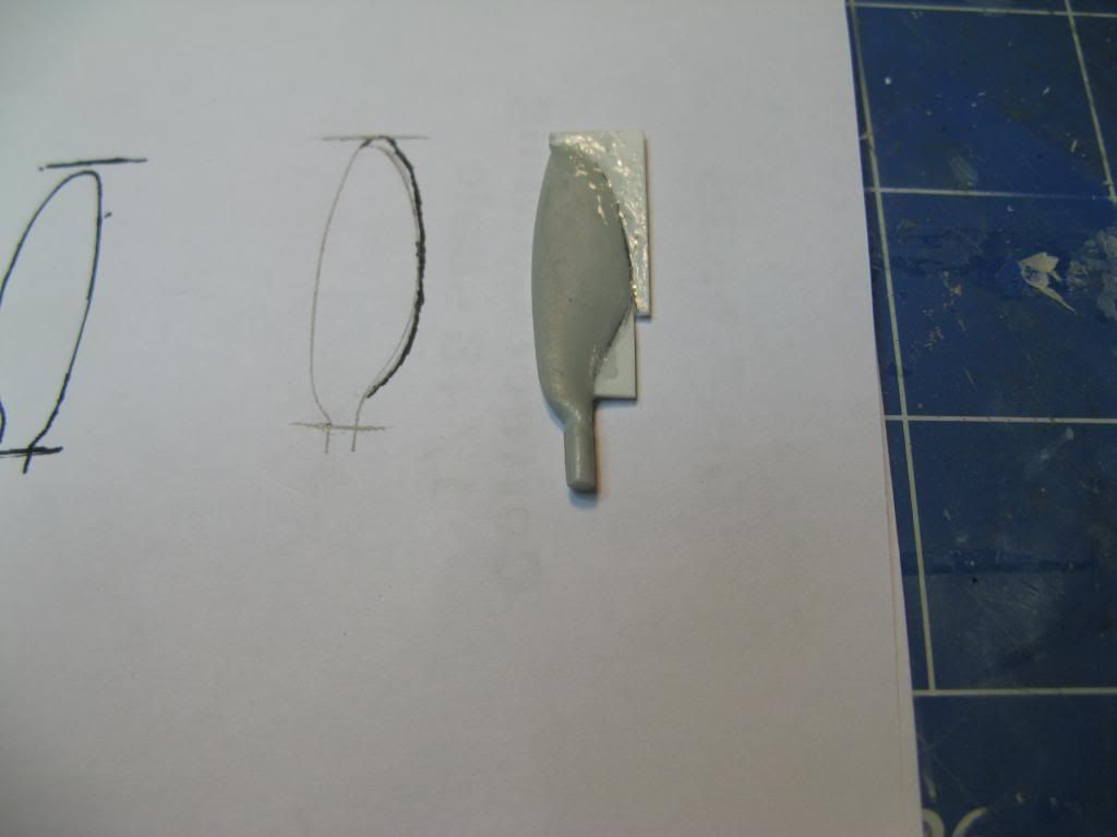
This was then shaped to match the drawing and the trailing edges thinned down.  Here you can see the almost completed blade next to the original Dragon version.
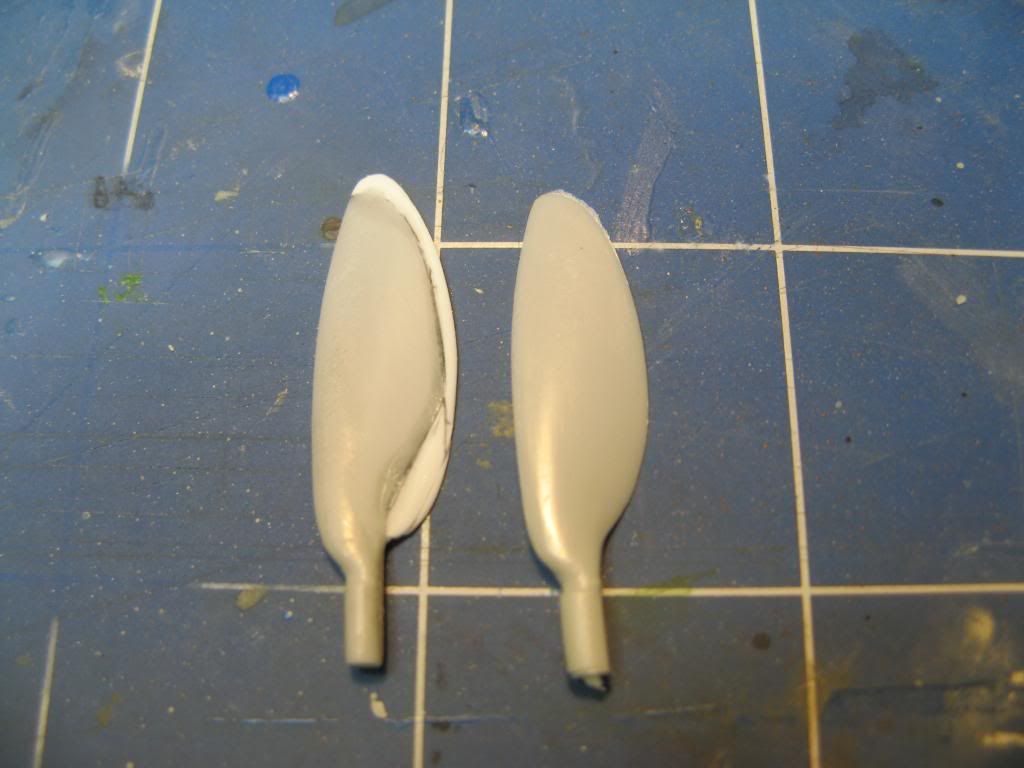
It's taller, more pointed and slightly wider.  Once finished it will be cast in resin to make exact duplicates.

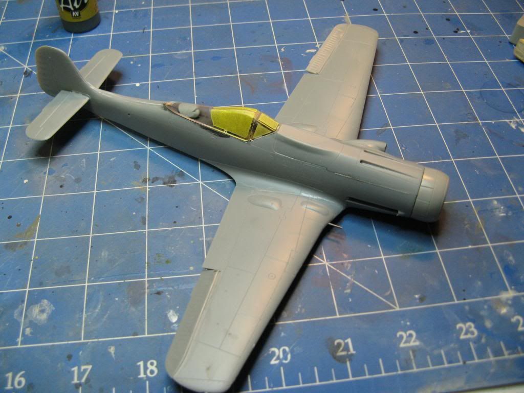
With the propeller blade completed I finished up the main assembly by gluing the wings on.
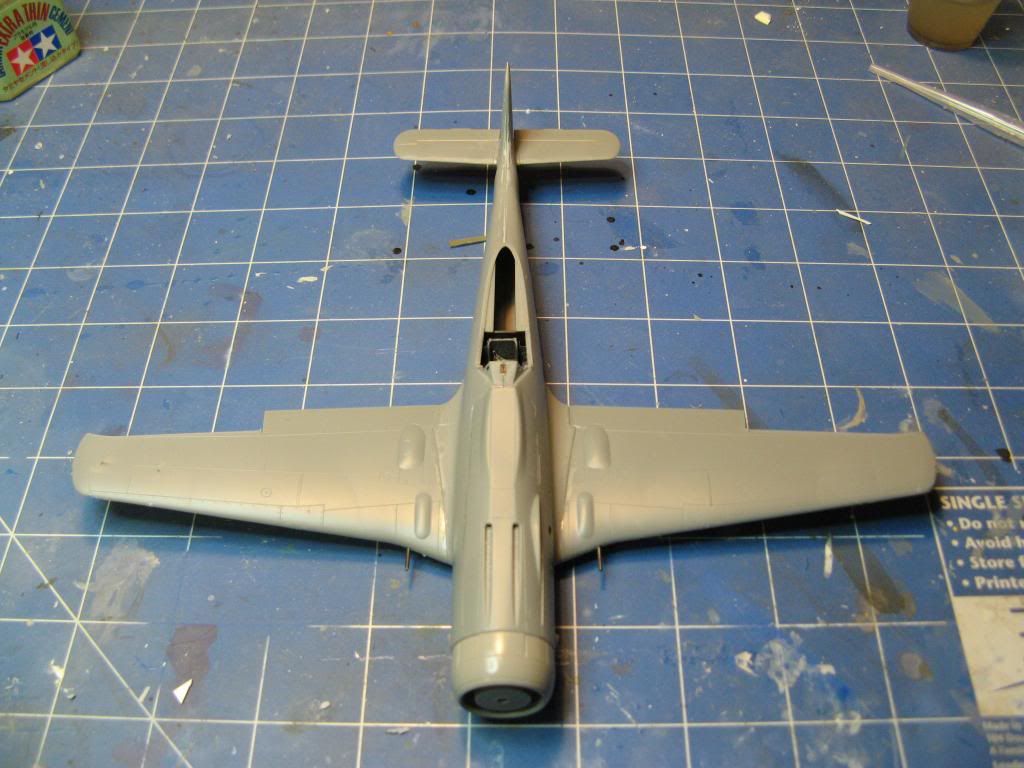
The wing and tailplane joints were pretty good.  A little more assembly and we're almost ready for paint.
In the next update we'll get some paint. and decals on.

On to part 5.

Saturday, 15 February 2014

Hobby Boss 1/48 Ta-152 C-0 - Part 3

Back to part 2

Welcome back.  In this update I work on the rear of the engine, start work on the wings, sort out the radiator and fix a large gap in the wheel wells.
Power Egg

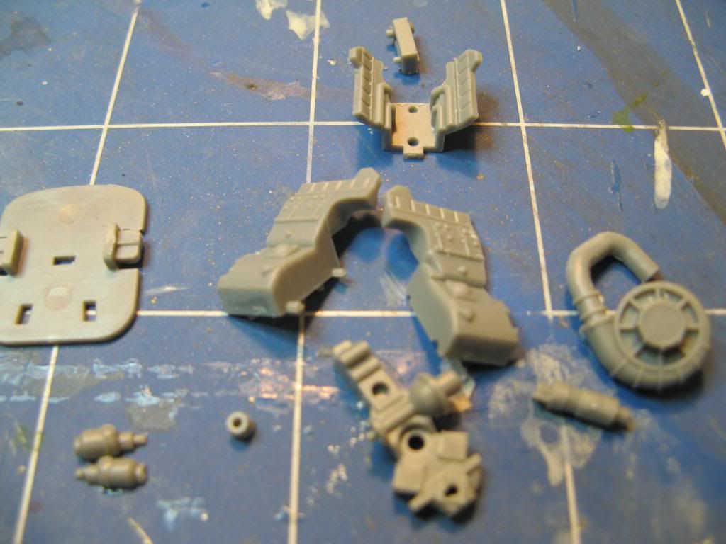
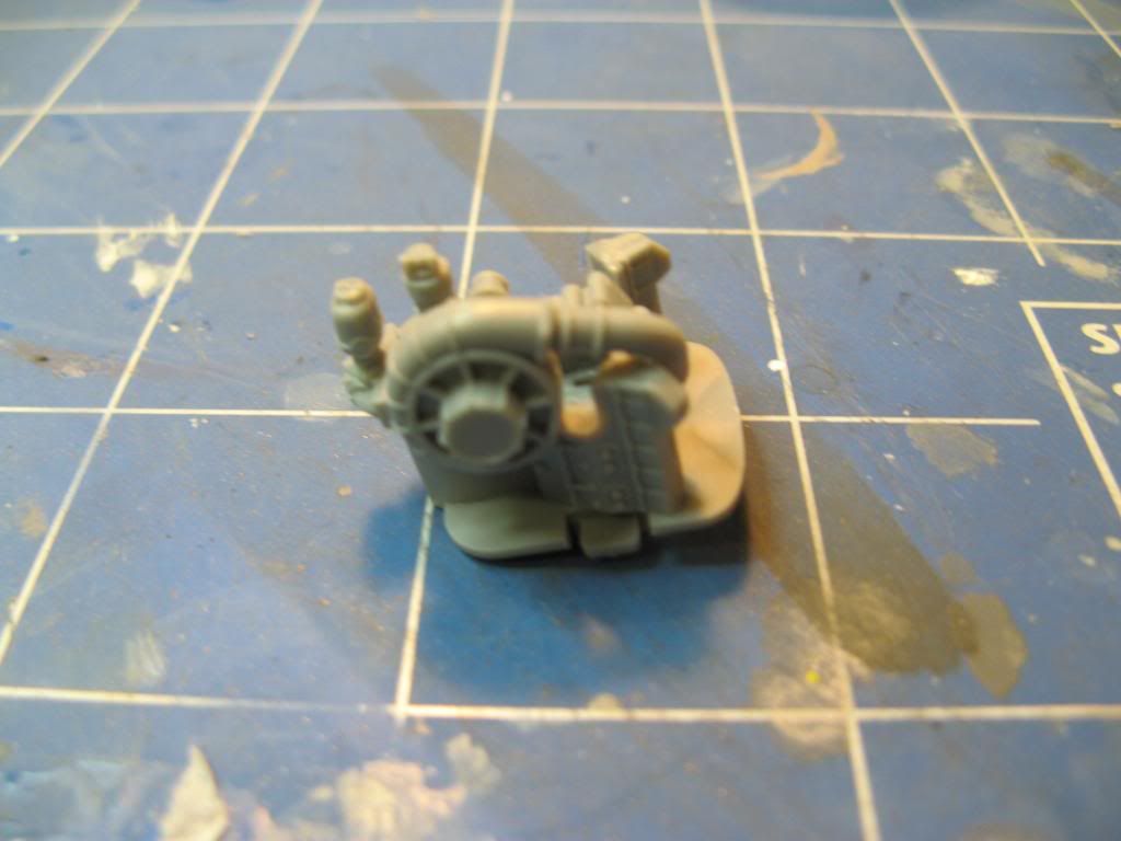
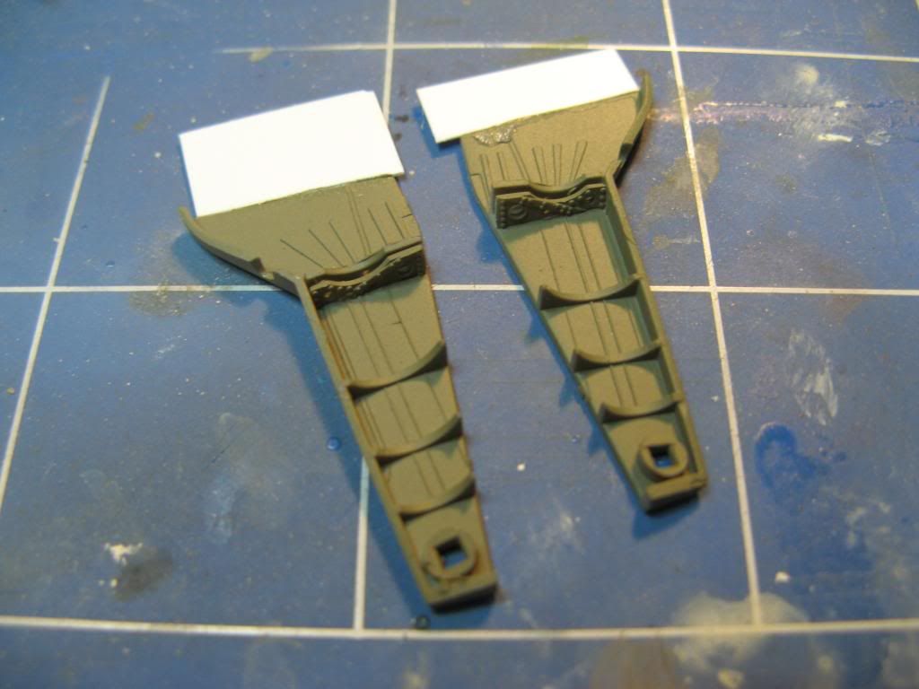
In the Ta-152 and in the Fw 190D from which it is derived the rear of the engine can be seen through the wheel wells.  Hobby Boss have allowed for this in the form of the rear part of a DB603E engine.  This is quite details as can be seen from the number of parts required to assemble it.

It does assemble into a rather nice representation of the back part of the engine.  Pity there's no representation of the engine bearers though.

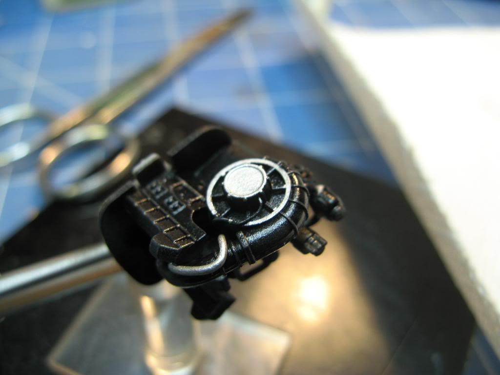
I did add a bit more detail using some lead wire before painting it.

Winging it

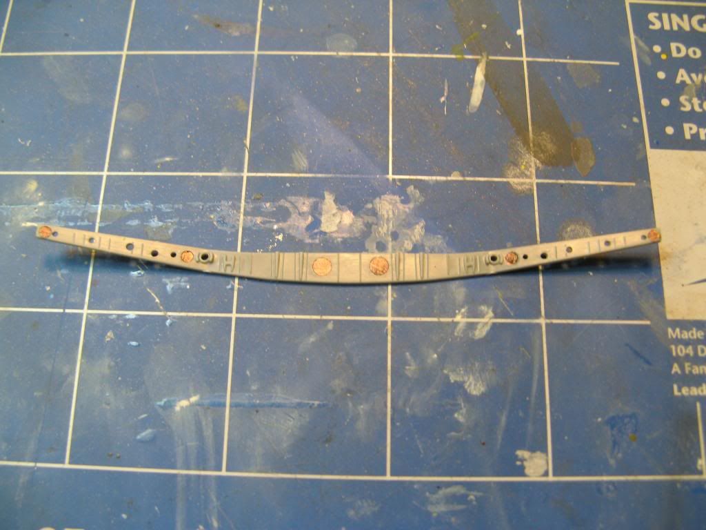
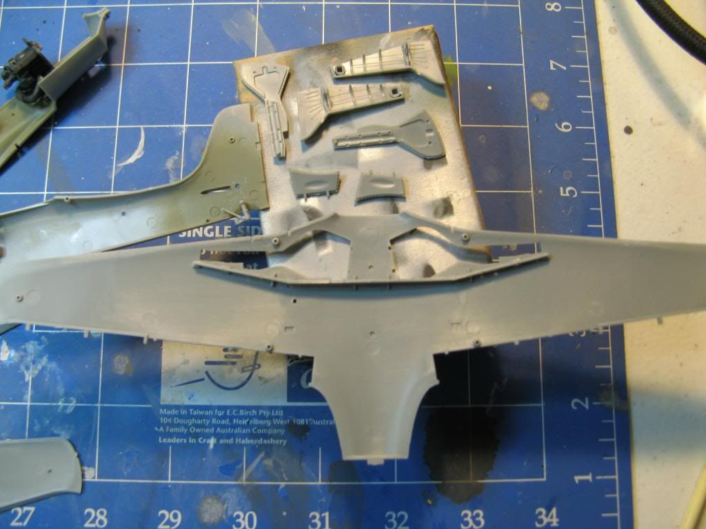
Assembly of the wings commences with the main spar which sits at the rear of the wheel wells.  This part had six ejection pin marks which needed to be taken care of.  I've coloured them in with a black marker pen to make them easier to see and to to indicate when they have been sanded out.

The lower wing section is moulded with gates that sit above the gluing surface.  Care is needed to remove these without making a dip in the plastic.  There was also a fair amount of flash on the leading edge which needed sanding off.

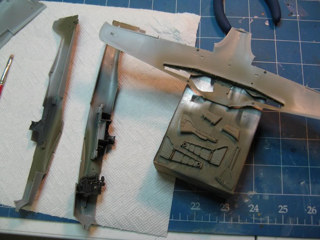
Given the wheel wells were to be painted RLM 02 grey I took the opportunity to prepare the insides of the gear doors too.  Also I removed the bottom section of the tail wheel.  Remember I have posed the rudder pedals off centre so I am going to have to reattach the tail wheel off centre as well.

Don't Blow a Fuse

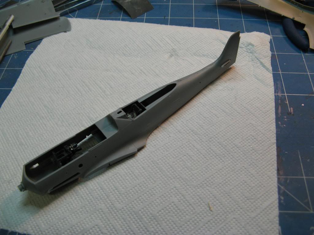
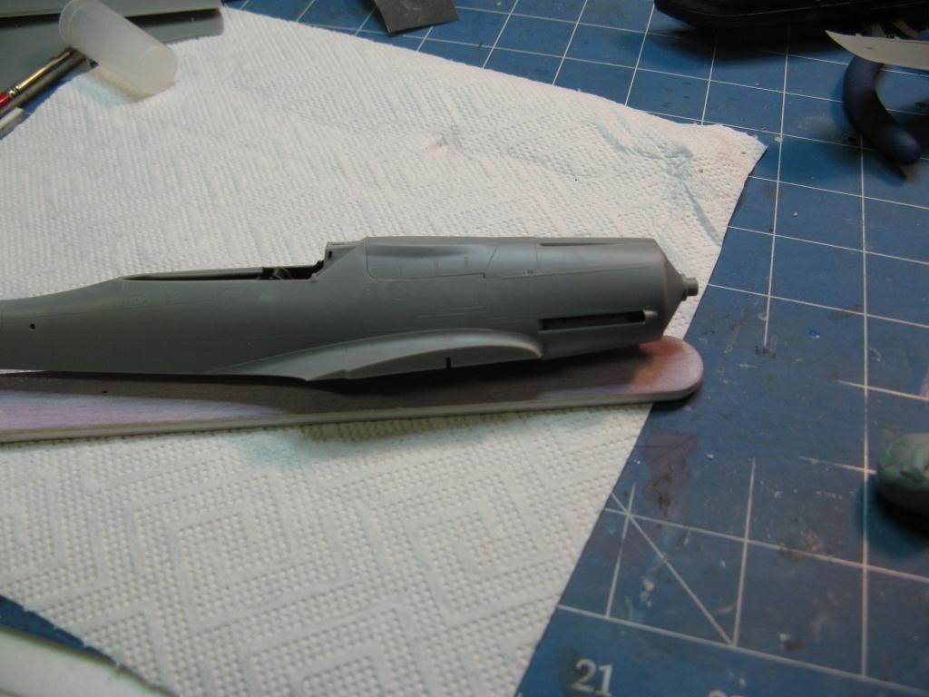
After painting the internals the fuselage was glued together.  The fit was pretty good but there was some pressure needed on the instrument shroud which I tacked with super glue before gluing the rest.

The cowl was then glued in place.  Hobby Boss give you two cowls - one has a large hump on the left hand side and the other a smaller hump.  This is because the supercharger of the production, C-1, model was larger as it was to use the DB603LA engine.  For a this pre-production, C-0, model the cowling with the smaller hump is correct since the DB603E was used.  The fit was pretty good.

Amputation

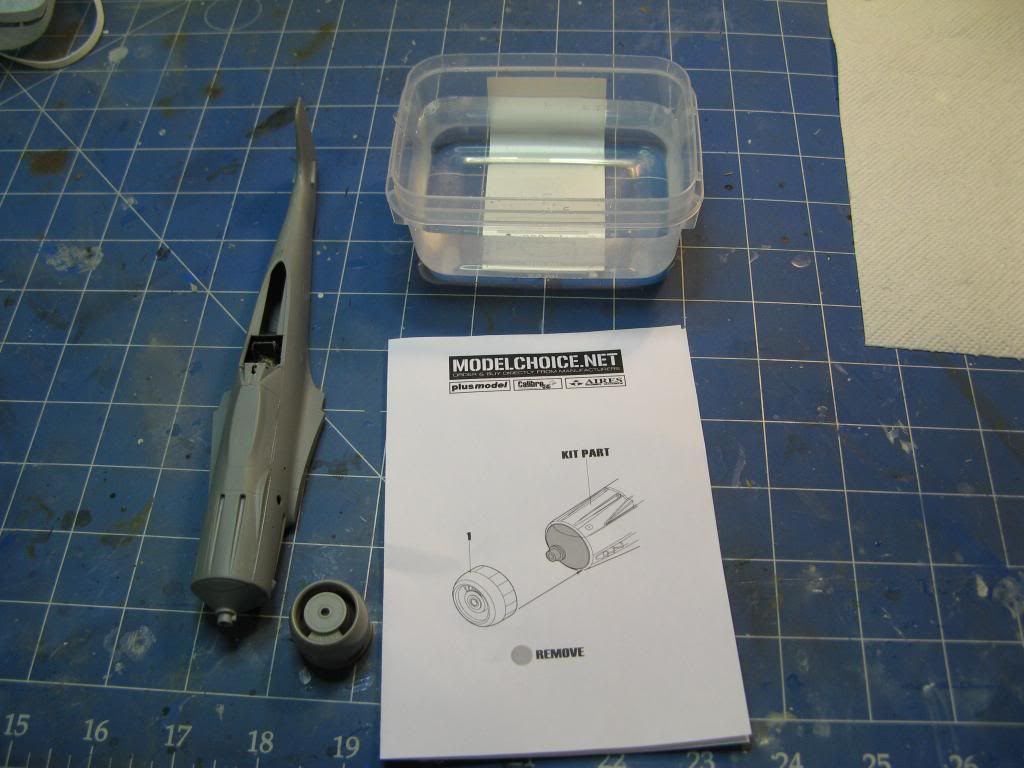
I mentioned in an earlier part that the Hobby Boss kit has the wrong radiator arrangement.  This is corrected with a replacement from Quickboost.  Here the patient is being prepared for surgery.  The tub of water is for sanding the resin replacement.  It keeps the dust down if you sand the resin wet.

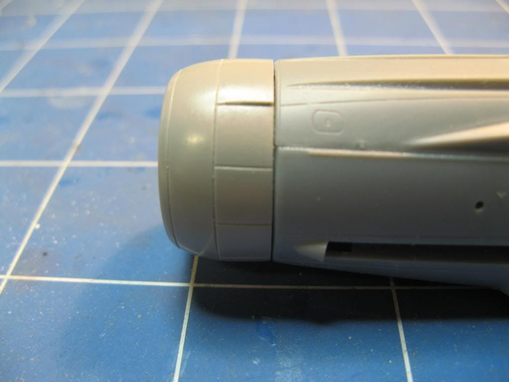
I first cut off the nose of the kit where the radiator assembly attaches.  This was done with a razor saw and carefully sanded square.  Then I used a razor saw to remove the casting block from the resin replacement and very carefully sanded it square using coarse wet and dry sand paper and plenty of water.  Once dried the new resin radiator assembly was glued onto the fuselage.  I am happy with the fit - enough of a gap to give the impression that the radiator cooling flaps can move.

The Grand Canyon Appears

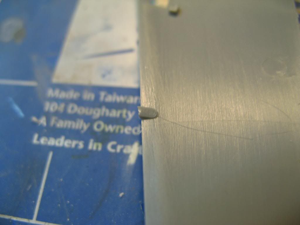
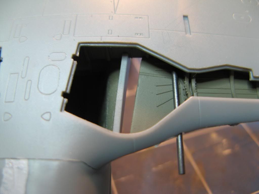
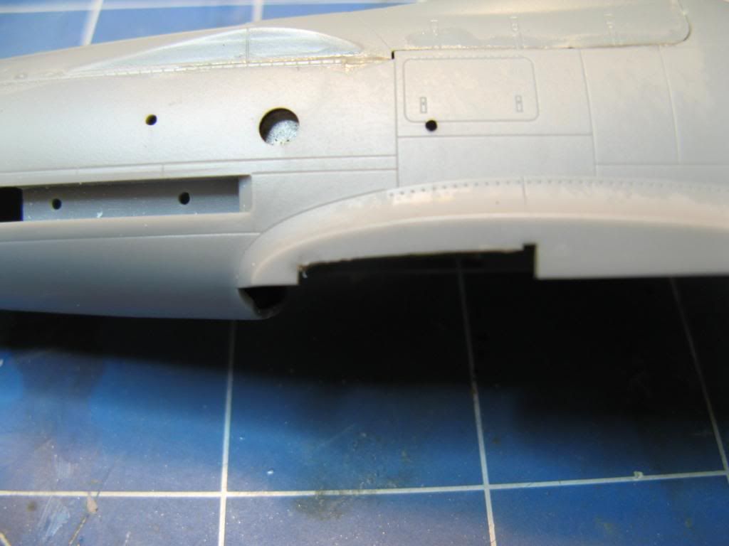
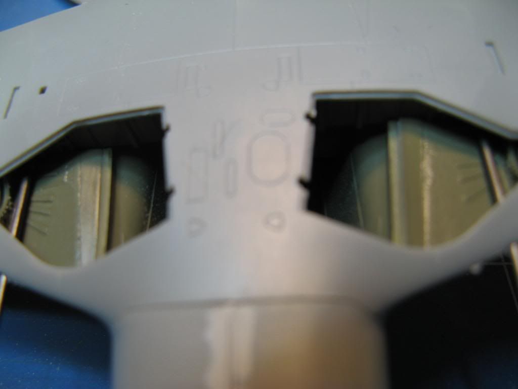
When I test fit the lower wing to the fuselage with the wheel wells in place I noticed the first major issue with the fit of this kit.  There is a massive gap between the wheel well and the wing mating surface on the fuselage.  Check out the amount of daylight you can see!

This called for extreme corrective action.  First plasticard sheet was used to extend the length of the wheel well.  I made a bit of a mess with the glue but I can clean that up later.

Once the glue had dried this sheet was then carefully trimmed to fit and a lip was glued onto the forward section.  The wheel wells were then dry fit and with a black marker were used to draw a notch on the fuselage wing mating surface.  This notch was then carefully cut out with a scriber and a sharp knife.

The wheel wells and inside the fuselage where they will mate was give a quick spray with RLM 02 grey and, hey presto, the gap has been taken care of.

That's all for this update.  In the next update I'll tackle the propeller and get the main assembly completed.

On to part 4.

Sunday, 26 January 2014

Academy 1/48 Mig-29A - Part 13

Back to part 12

Use of Weapons

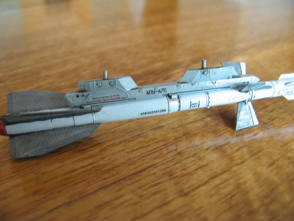
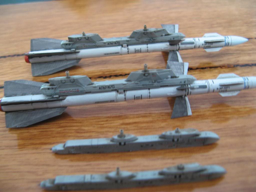
The decals were put onto the AA-10C missiles and their pylons after giving them a gloss coat.  Another gloss coats was applied and once that was dry the missiles and the pylons were given a wash of Flory Models Dark Dirt.


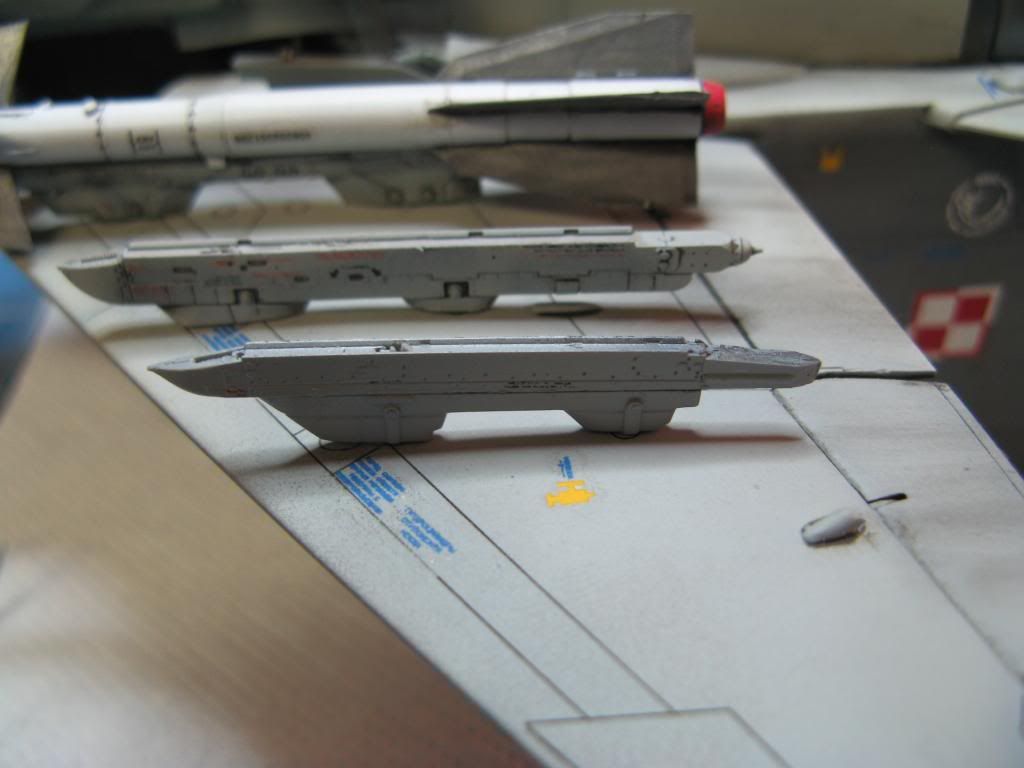
The same was done for the pylons for the AA-11 missiles.  You can see them in front of the AA-10Cs below.

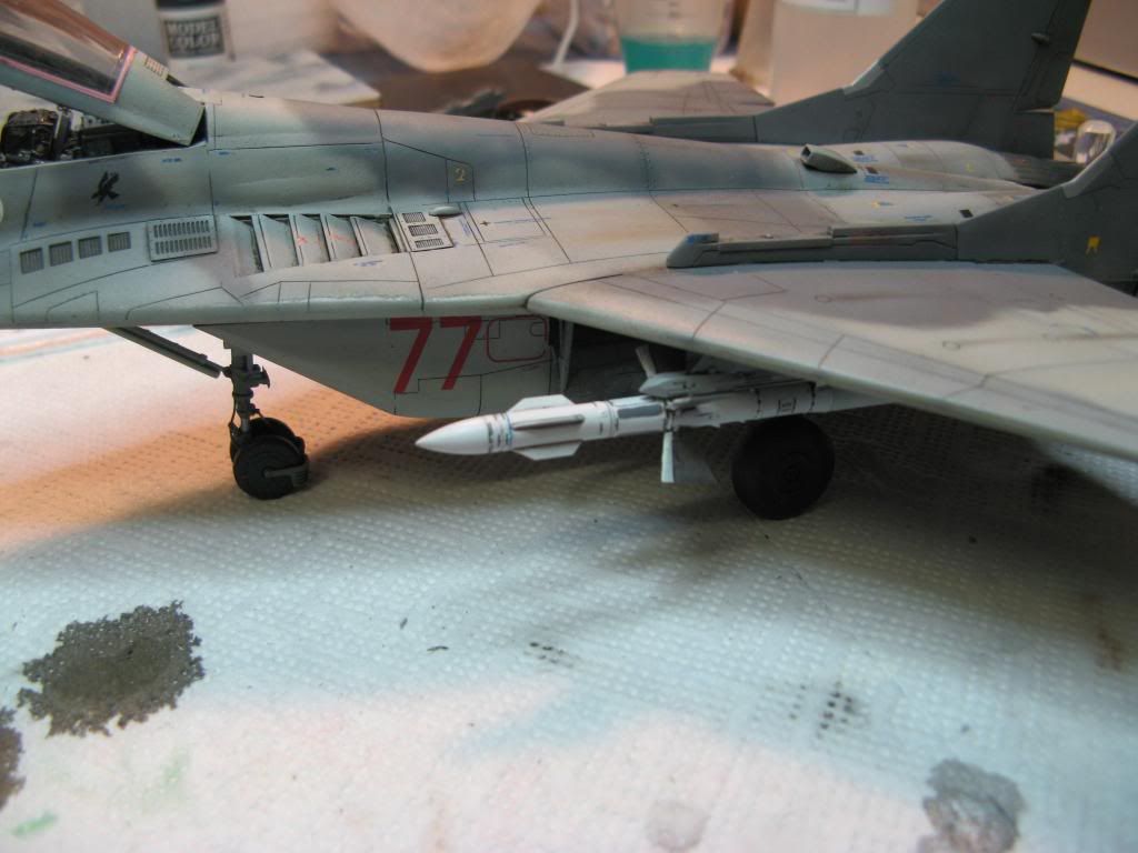
After a coat of matt varnish these were then attached to the model.

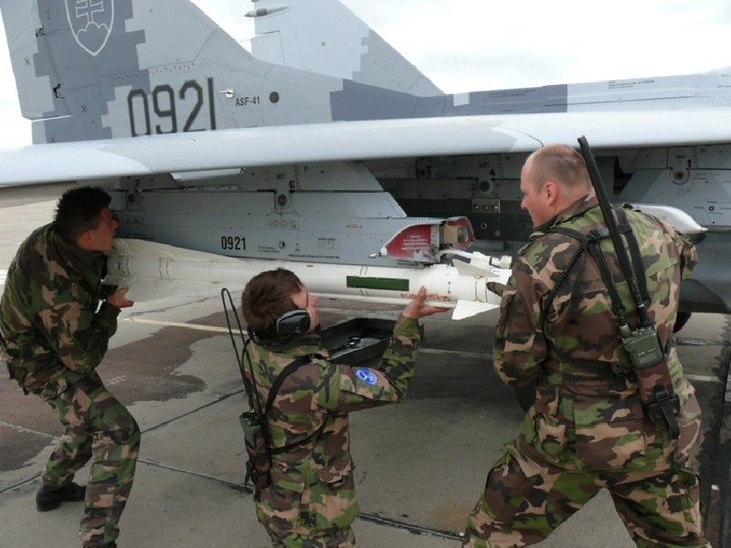
The AA-8 missiles require an APU-60 pylon to be launched and Eduard supply these to go with the missiles.  However in order to launch them from a Mig-29 there is some correction required to these.  This is what and APU-60 should look like

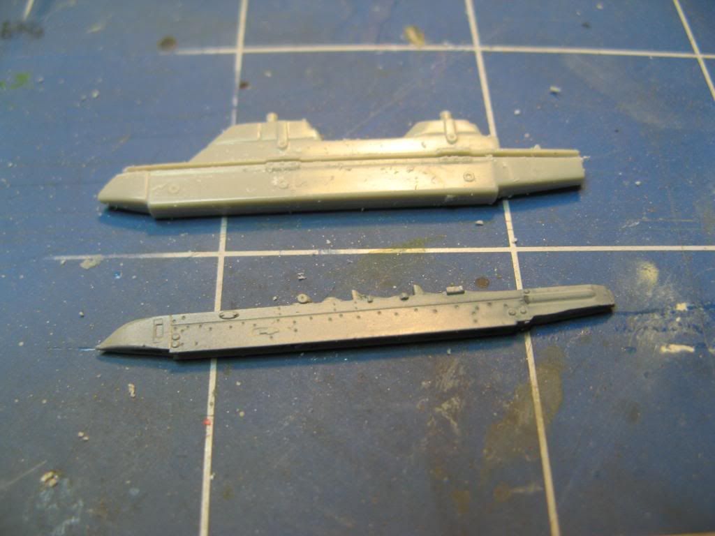
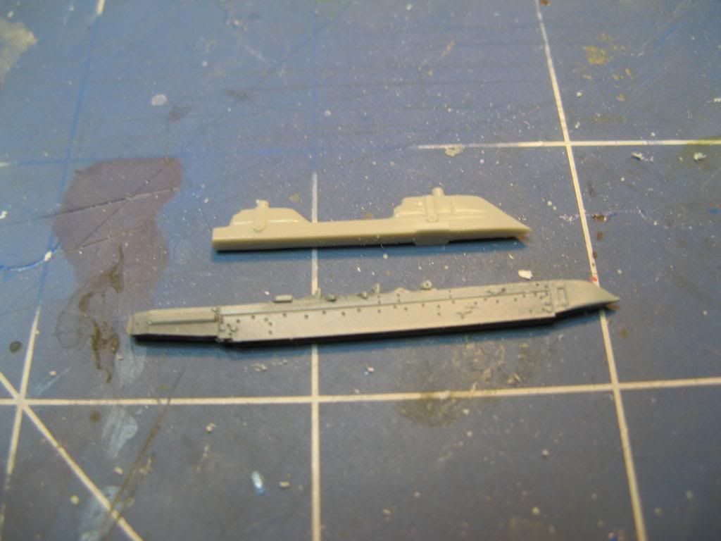
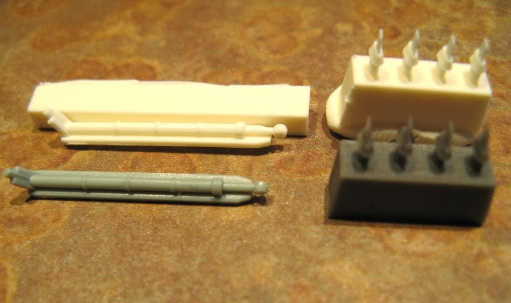
The kit launchers are too big and are not very detailed but they do have the right attachment points to the wing of the Mig 29.  My solution was to use the attachment supplied with the kit and the launcher supplied by Eduard.  You can see the kit part at the top of this photo and the Eudard part underneath it.

This required removal of the kit launcher from the attachment and mating it to the Eduard launcher.

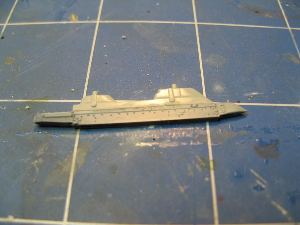
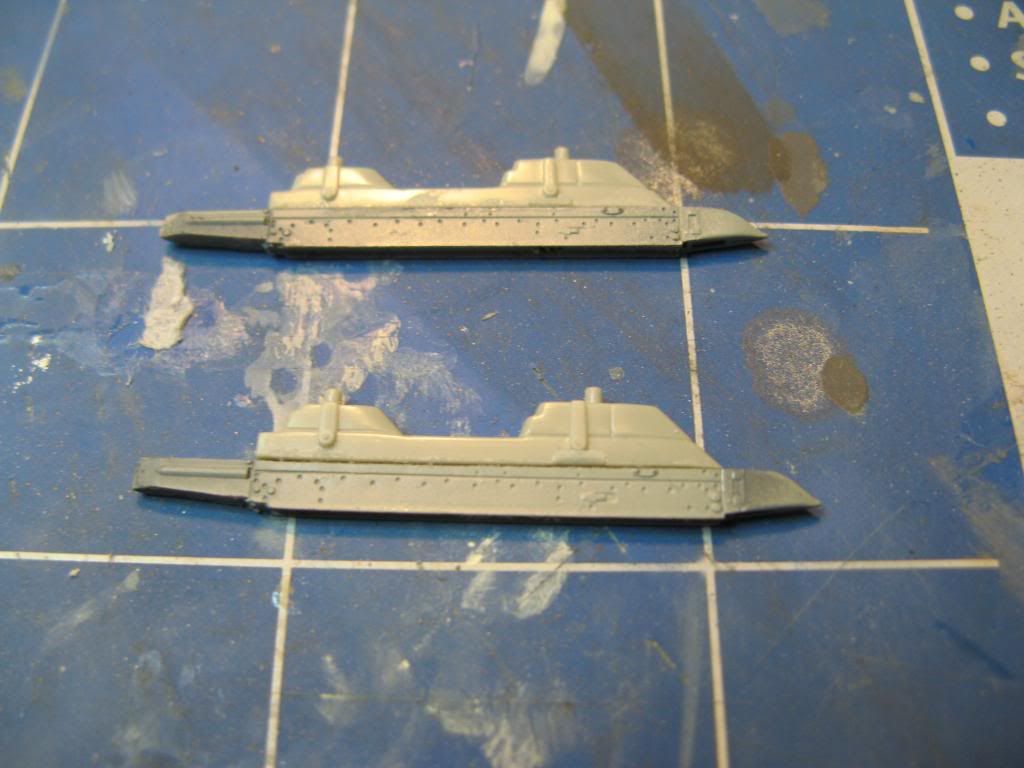
After a bit of squaring up and careful gluing I now have an accurate APU-60 suitable for a Mig 29.

I used the same procedure to make a second.

These were painted up and decals were applied.  Here's one temporarily attached to the wing as the decals set.

Good Twin or Evil Twin?


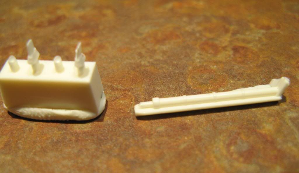
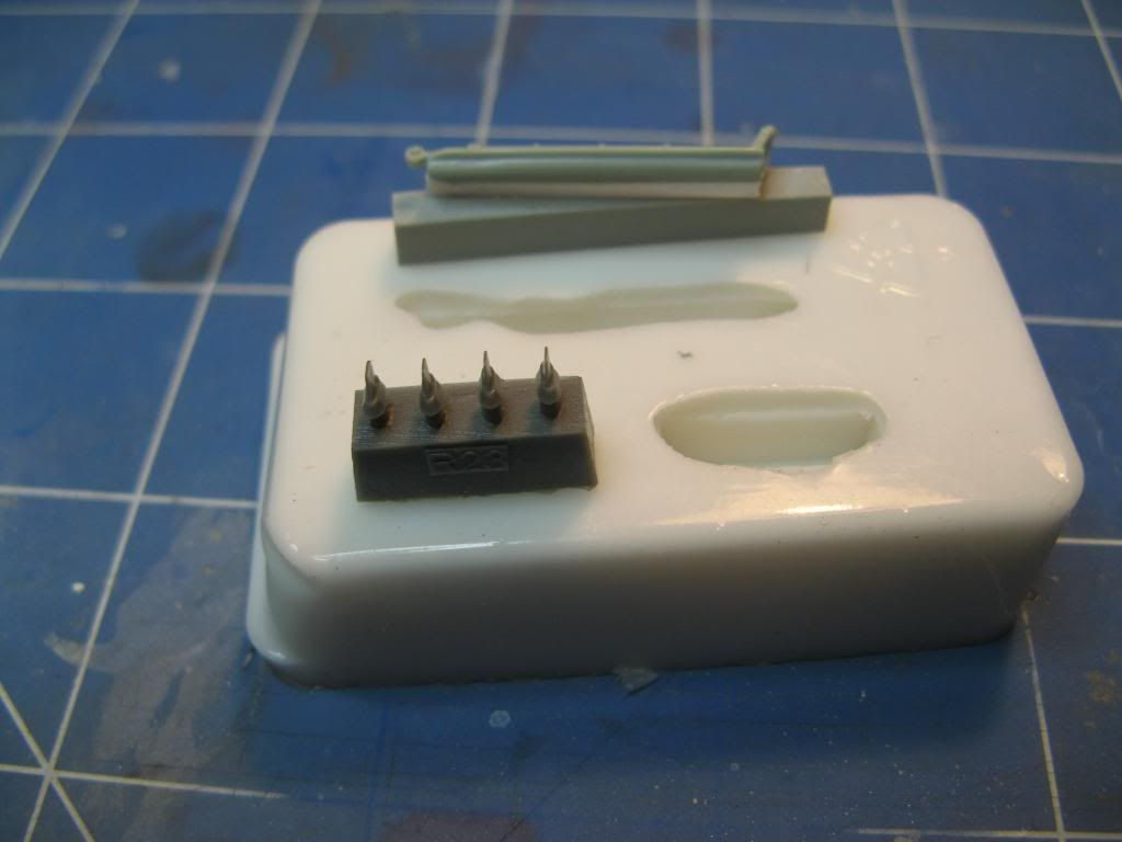
You might remember that I used a part of the kit as a mask for the front wheel well.  Since this part underwent surgery to make it act as a mask I needed to get a replacement.  The Eduard 1/48 Mig-29UB has this same part so I decided to copy it, and some blade antennas I also need, in resin.


For a more detailed tutorial on how I made the mould and did the resin casting click here.

Here's one of the resin blade antennas attached...

...and here's the replacement nose gear door/strut.

There's still a bit to do.  I had to write it all down so I don't forget anything.  It's all of the detail bits really so we should not be too far from a final reveal.

Tuesday, 31 December 2013

Making Silicone Moulds and Casting in Resin

Introduction

When I was building my 1/48 Mig-29A I used one of the front wheel door parts as a mask while I sprayed the camo.  I (wrongly) assumed that there was a replacement in the Aires wheel well set I installed and to make the part fit I altered it.  This made it useless for its intended purpose.  I did have a the Eduard 1/48 Mig-29UB which has the same part so I could have used that, but that would render that kit useless.  So, I decided to cast a replacement part from resin.  As I was going to do this I thought it might be a good idea to make this tutorial to show how easy it is to do.

Making the Mould

What you need

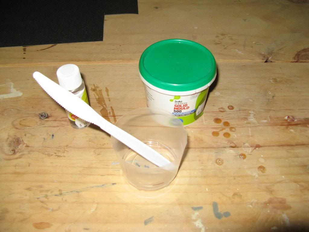
In order to make the mould you're going to need the following materials: Silicone Rubber, Catalyst, a clean mixing cup and a flat sided spatula (I used the handle of a disposable knife).

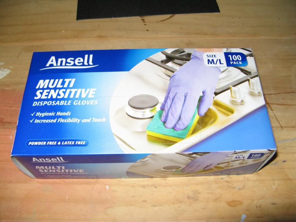
You're also going to need some latex or nitrile gloves to keep this stuff off your hands as it is really sticky and according to the directions it can be hazardous.  I have shares in this company so I recommend the brand :-)

Preparing the Master

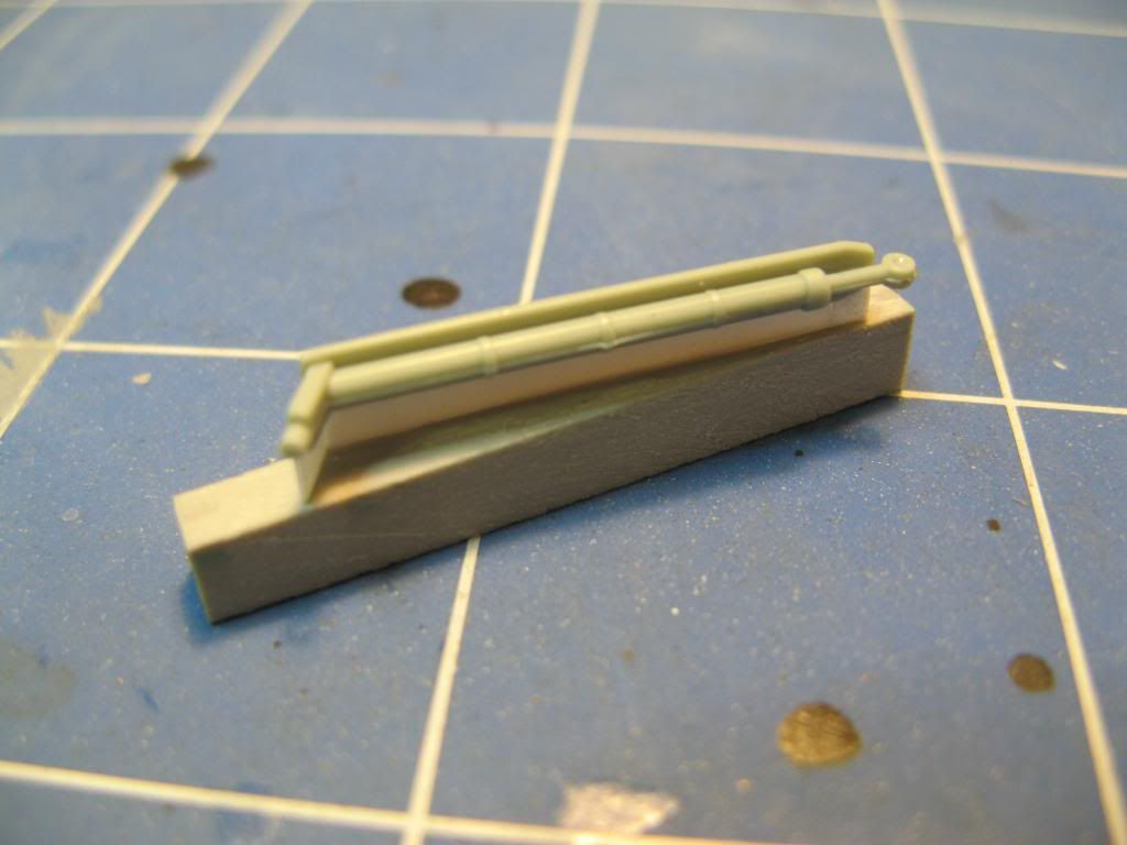
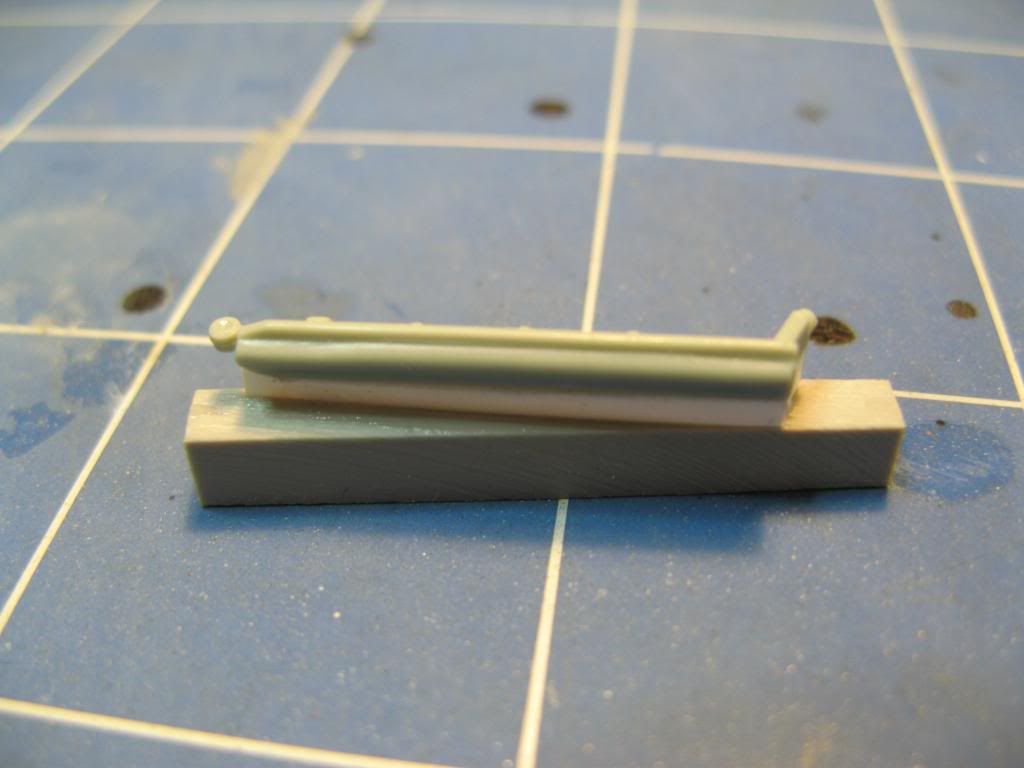
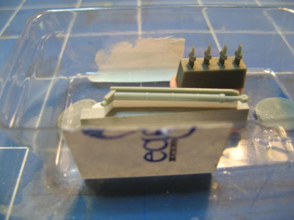
The part in question (the master) was given a cleanup and was temporarily cemented to some plasticard.  This was then glues to a resin block with super glue.  There is a small hole in one end and since this would create problems getting it out of the mould it was filled with a small amount of PVA.

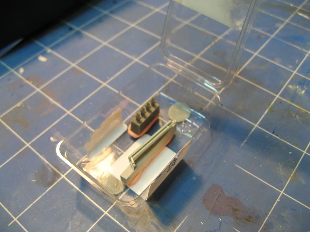
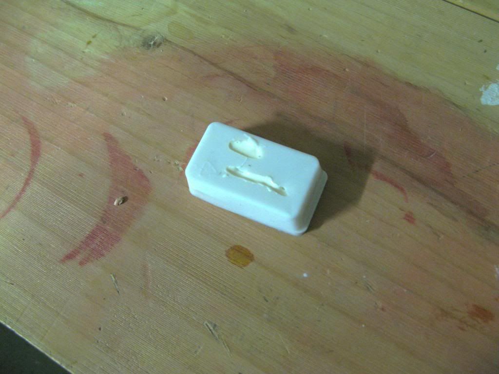
A suitable container for the mould was found.  In this case it happens to be a blister pack from a resin update set.  The master was stuck to the bottom of this using some plasticine.  You can also see that I have taken the opportunity to cast another part at the same time.

Pouring the Mould

I measured the length, width and depth of the container that I was using as the mould.  It was 6cm x 3.8cm x 2cm.  This give a volume of near enough to 40ml.  You can convert this to a weight of required silicone but since this is close to 1g per cubic centimeter I chose to work with the volume instead.

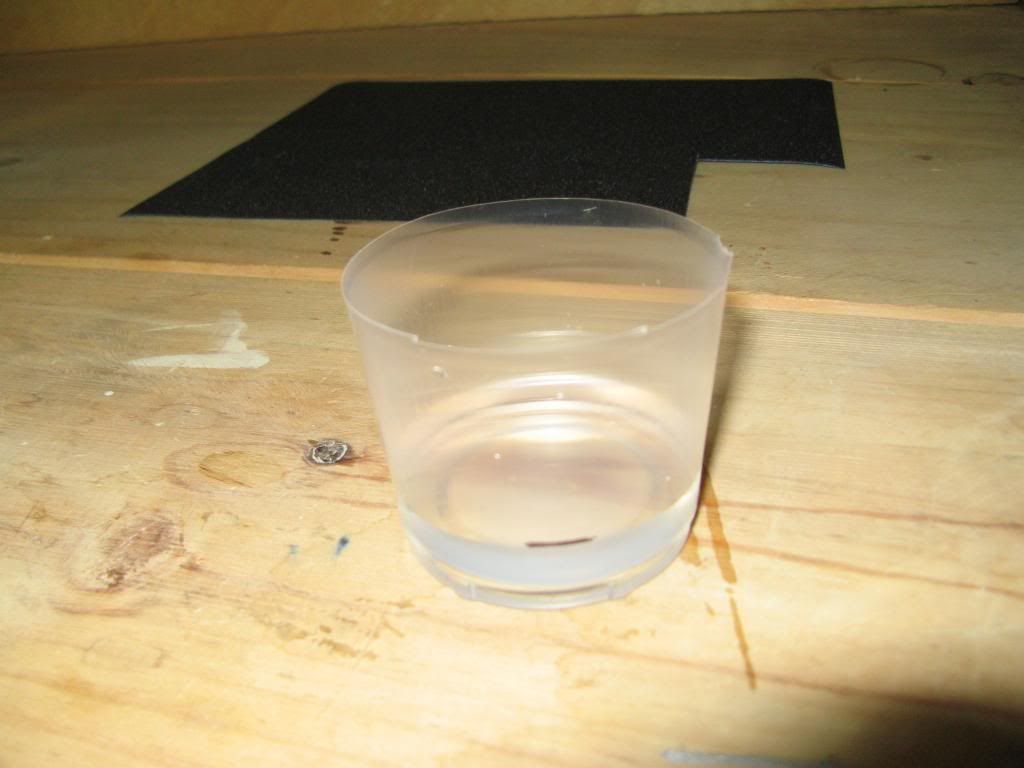
I measured out 40ml of water and poured it into my mixing cup. Using a permanent marker I marked where the water came up to.
The water was then discarded and the mixing cup dried thoroughly.

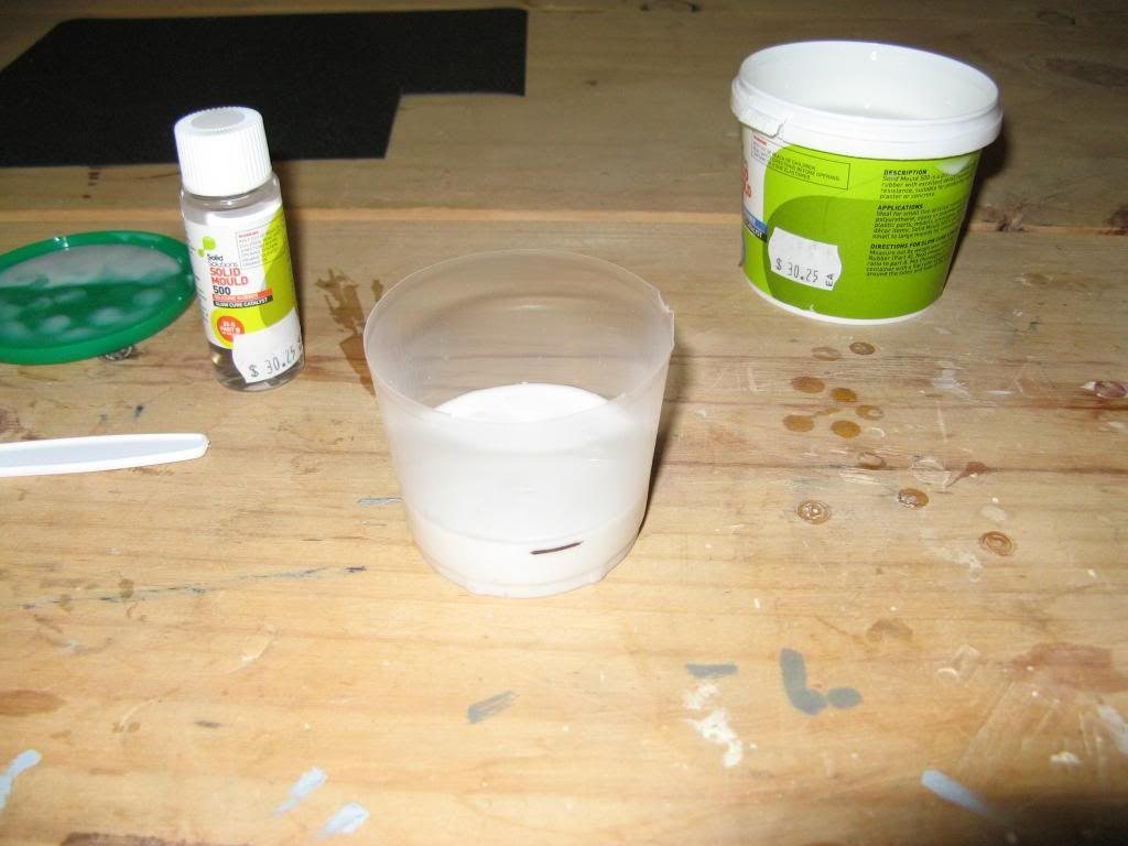
The silicone rubber was then poured into the mixing cup up to the mark.  You can see I overshot a little as this stuff is really thick to pour.

For the amount of silicone rubber I was mixing I added 1.2ml of catalyst to the raw silicone.  I then mixed it with the handle of the knife.  You should try not to get air into the mix but it is really difficult not to.  Professionals would put the mixture into a vacuum chamber to de-gas the silicone after it's mixed but I don't have that luxury.  Also make sure that you scrape the sides and bottom of the pot while you're mixing it.

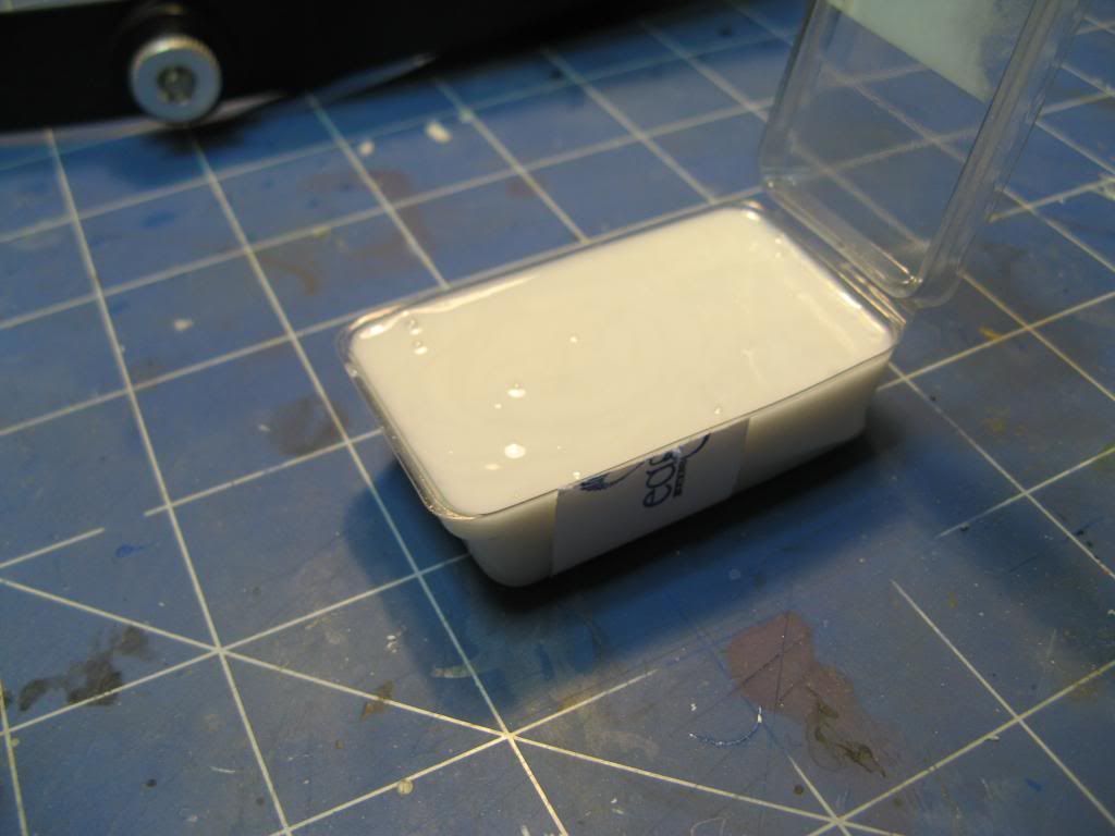
Once it was thoroughly mixed the rubber was then poured slowly into the mould.  Start from one corner and let the rubber flow slowly around the master.  This will minimise any chance of getting air bubbles.   Again, professionals would do a second de-gassing at this stage and again I didn't.  Once it is full set it aside for 24 hours to cure.

After it has cured you can remove the hardened silicone rubber from the container...

...and then remove the masters.

Casting in Resin

What you will Need

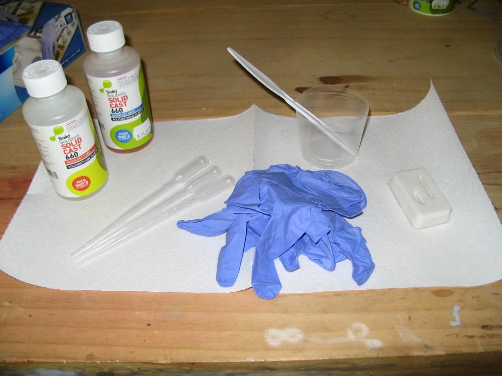
To do this part you will need.  Part A and Part B resin, latex or nitrile gloves, a container to mix in, something to mix with and either two measuring beakers or, as I am using, disposable pipettes with measurements on the side...and of course your silicone rubber mould.

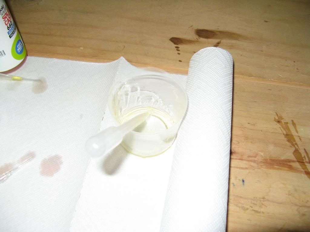
Put on the disposable gloves and measure out equal quantities by volume of part A and Part B resin.  Add these to the mixing cup and stir thoroughly.

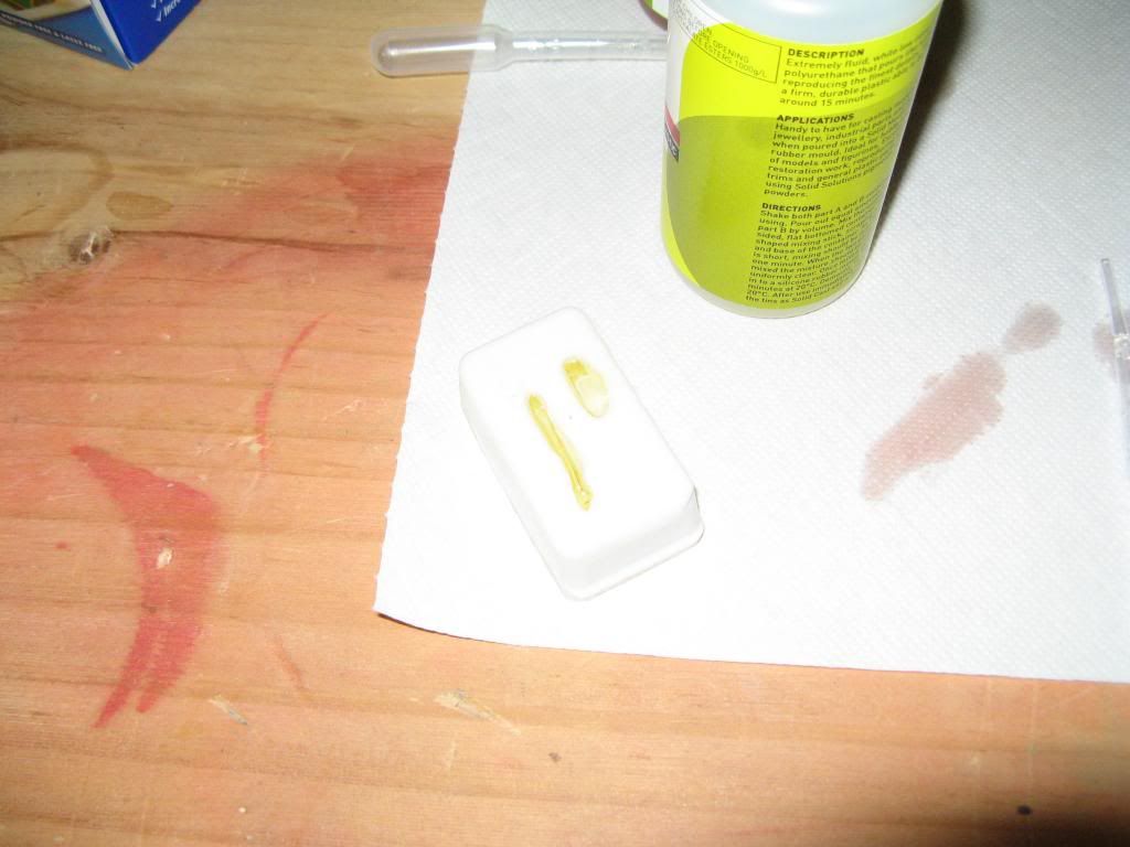
Once mixed pour the resin into the mould.  In my case I used a third pipette to transfer the resin to the mould.  Experiment with what works best for you.  The trick is to get the resin into all parts of the mould without getting any air bubbles.

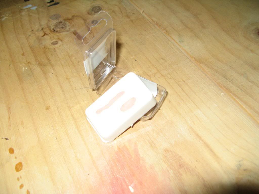
As the resin sets it will turn white.  Leave it for 20-30 minutes before removing it from the mould.

Success.  Perfect copies of the originals.

Be prepared for some failures though.

I hope that you have found this useful.