And We're Off...
I'm building this model at the same time as a friend of mine is building his. He's already built the engine so that's where I decided to start as well. The Spitfire XVIe had a Packard built Merlin 266 engine. Finding references for this specific engine did prove a challenge but eventually I did find some after trawling through images on Google. The Tamiya engine is quite amazing out of the box but there are a few places where more detail can be added.Construction started with the crankcase assembly. For a while I was puzzled as to why part H20 was not glued into each side of the crankcase. I admit that I considered gluing it, but after some consideration I decided that the good folks at Tamiya know what they're doing so I didn't glue it in the end. Later in the assembly of the engine we'll find out why it is not glued - well my theory anyway.
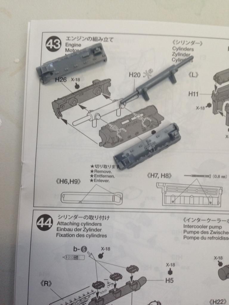
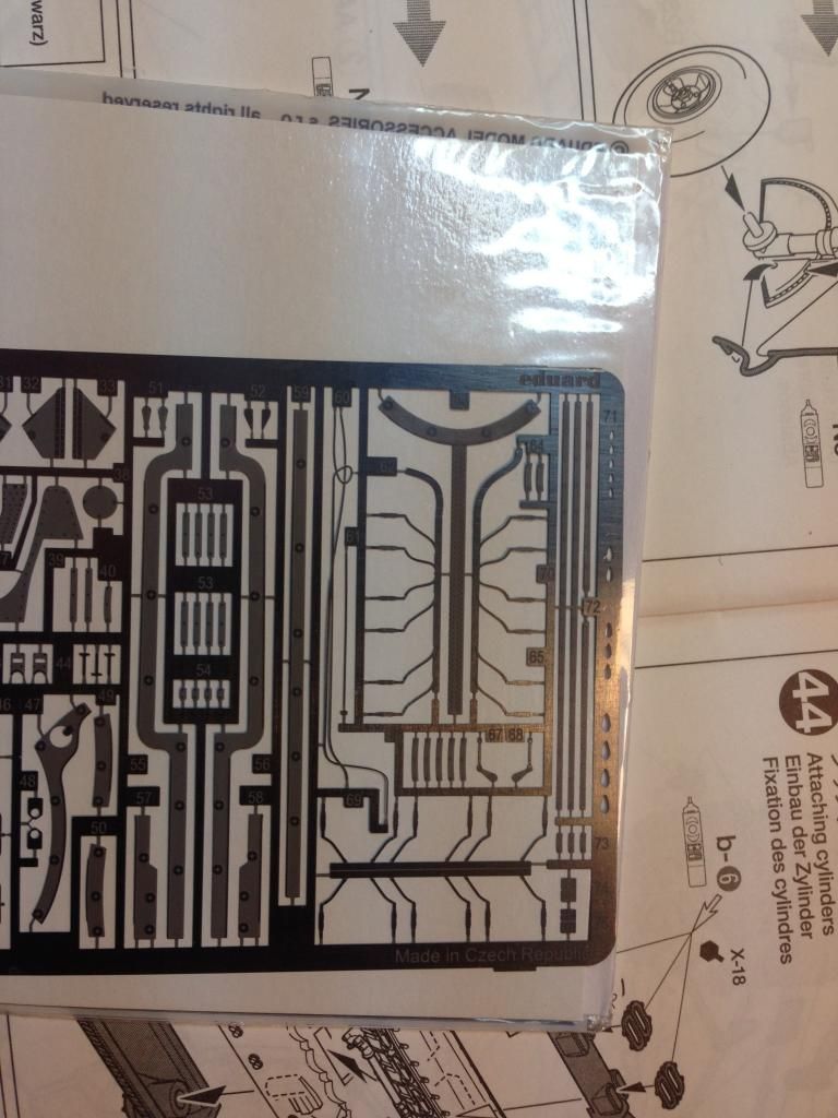
The Eduard exterior detail set comes with a wiring harness for the spark plugs. I didn't like the look of it for two reasons. Firstly, on the Packard Merlin 266 the harness which sits on the top is actually in two parts not one as the Eduard photoetch would suggest. The second reason is being photoetch it's flat.
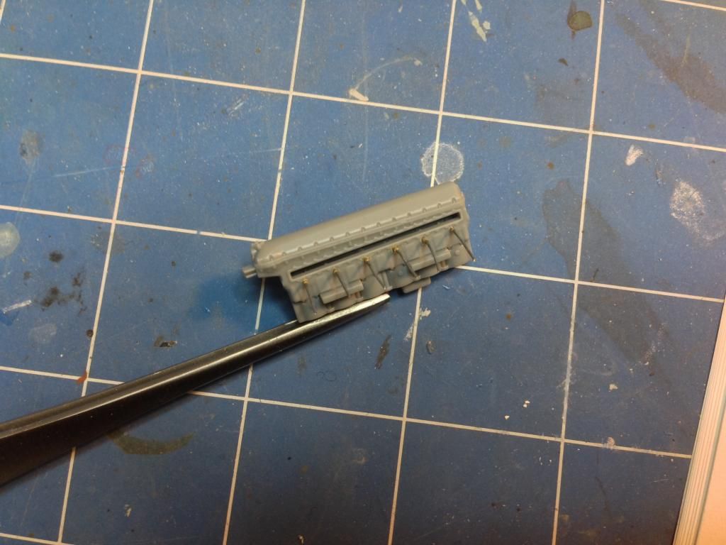
The solution was to build my own. I started by using 0.6mm brass tubing to replicate the spark plugs.

This was then given leads made from 0.4mm lead wire.
Then the cylinder blocks were cemented to the crankcase. The sparkplug leads were fed carefully around the manifold.
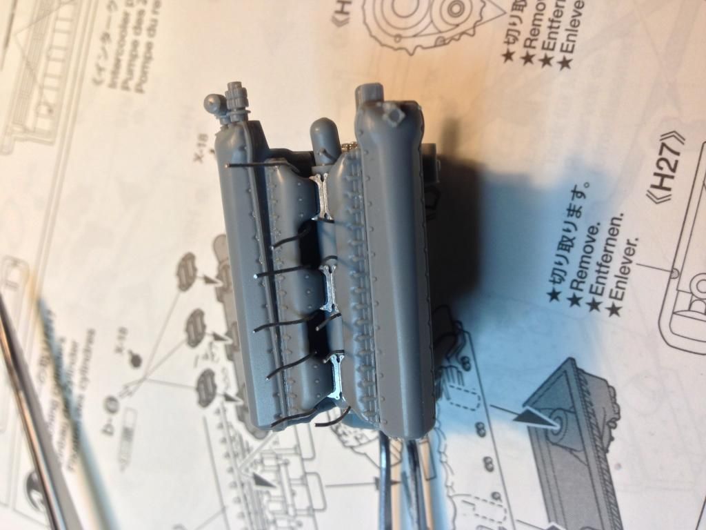
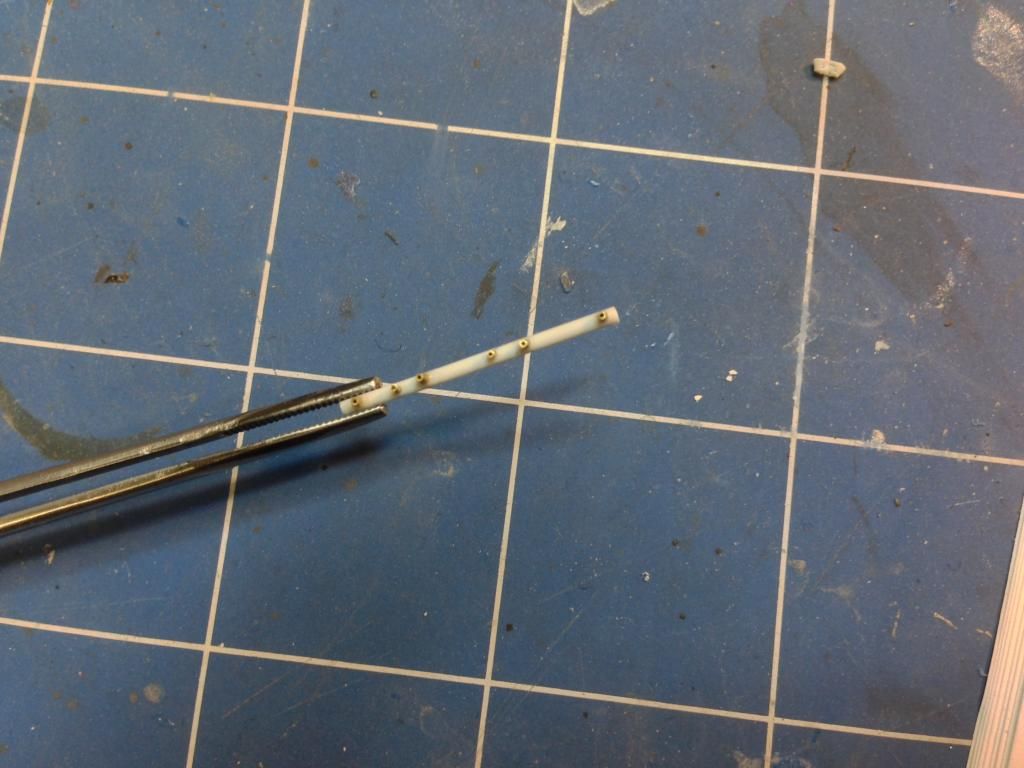
These leads needed a harness to be wired into so I had to scratch make them as well. The main parts of the harnesses were made of 1.2mm plastic rod which was carefully drilled to accept some 0.6mm brass tubing.
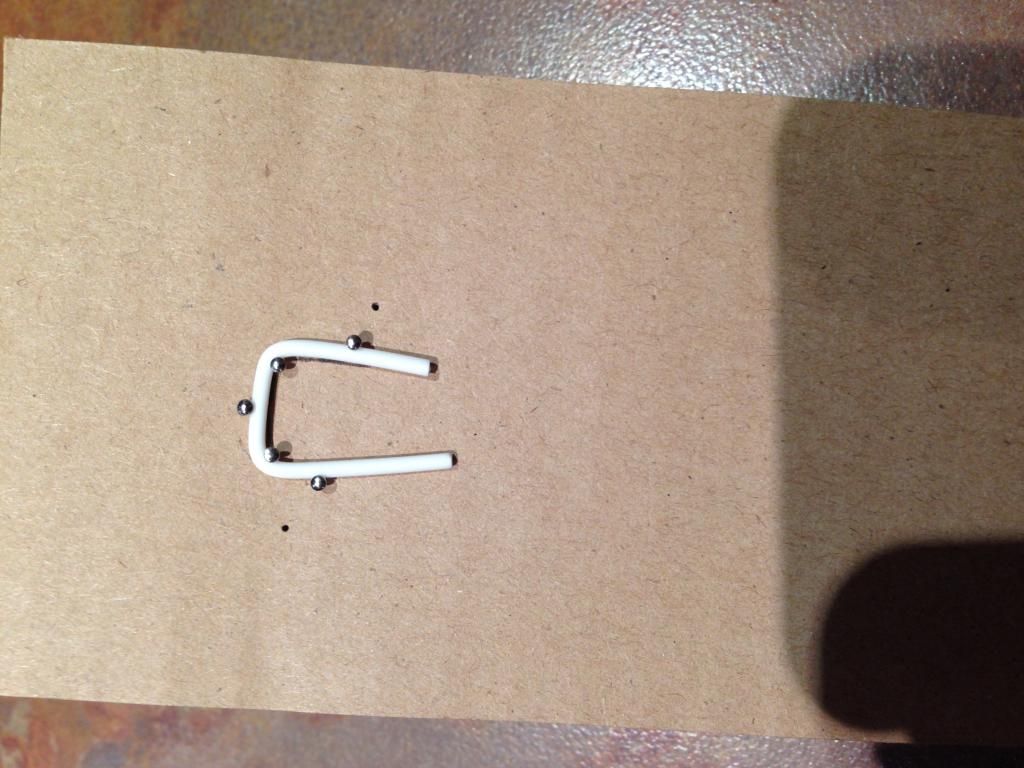
The upper wiring harnesses are connected by a conduit that is thicker than the harnesses. This was made out of 1.6mm plastic rod but it needed to be the correct shape. I started with a small piece of rod and held it in place with a few pins on a piece of cardboard. I then heated it with a hairdryer set on hot and carefully bent the plastic until it was the shape I needed and then pinned it so it stayed in that shape. It was then allowed to cool. My theory was it would stay in that shape once it cooled and that was sort of true.
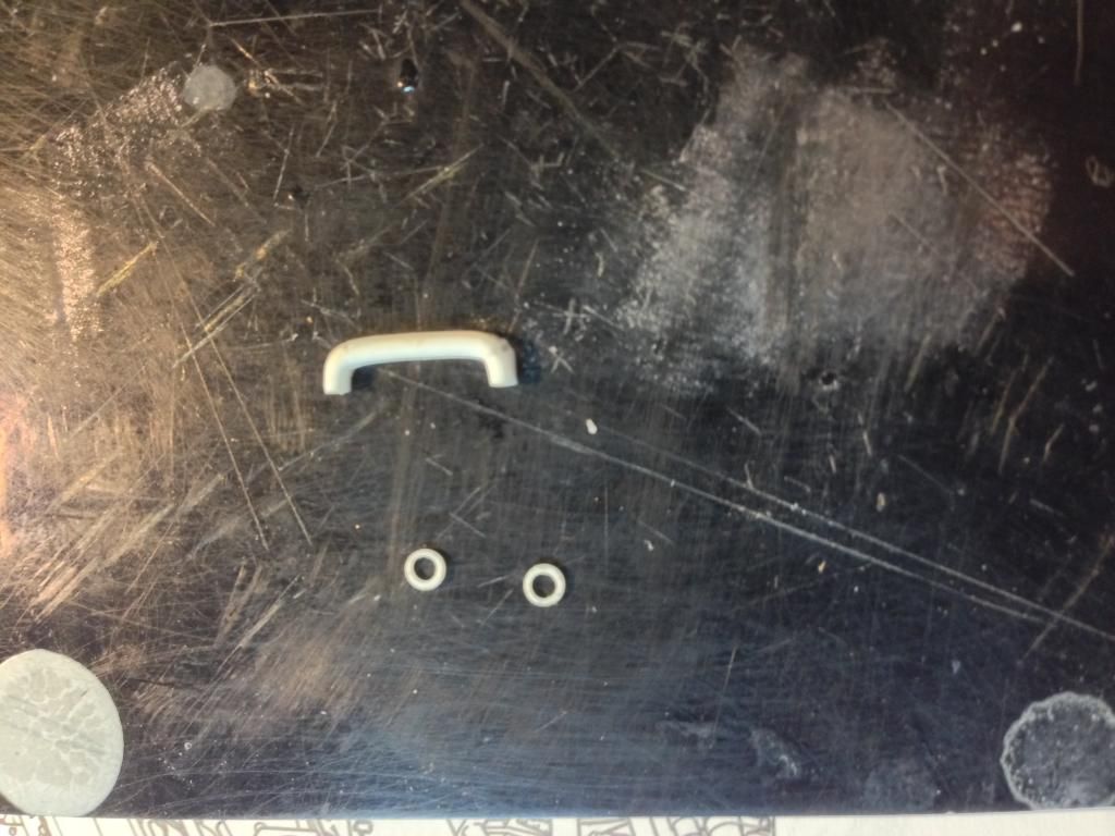
Once this was the right shape I cut it to size and made two collars for it using the Waldron punch set.
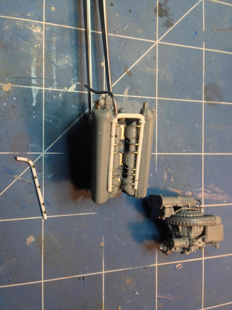
I could then assemble the harness and wire it into the sparkplug leads. Here's the assembled harness on the top after wiring it in. Next to the engine is one of the side harnesses and the supercharger assembly. Extra plumbing was added to that as well. Notice that the pipes leading out of the side harnesses face forward and one of then is slightly offset to clear the intercooler pump.
The engine assemblies were primed and then given a coat of Citadel Boltgun metal. This would give a metallic undercoat which would show through chips on the engine.
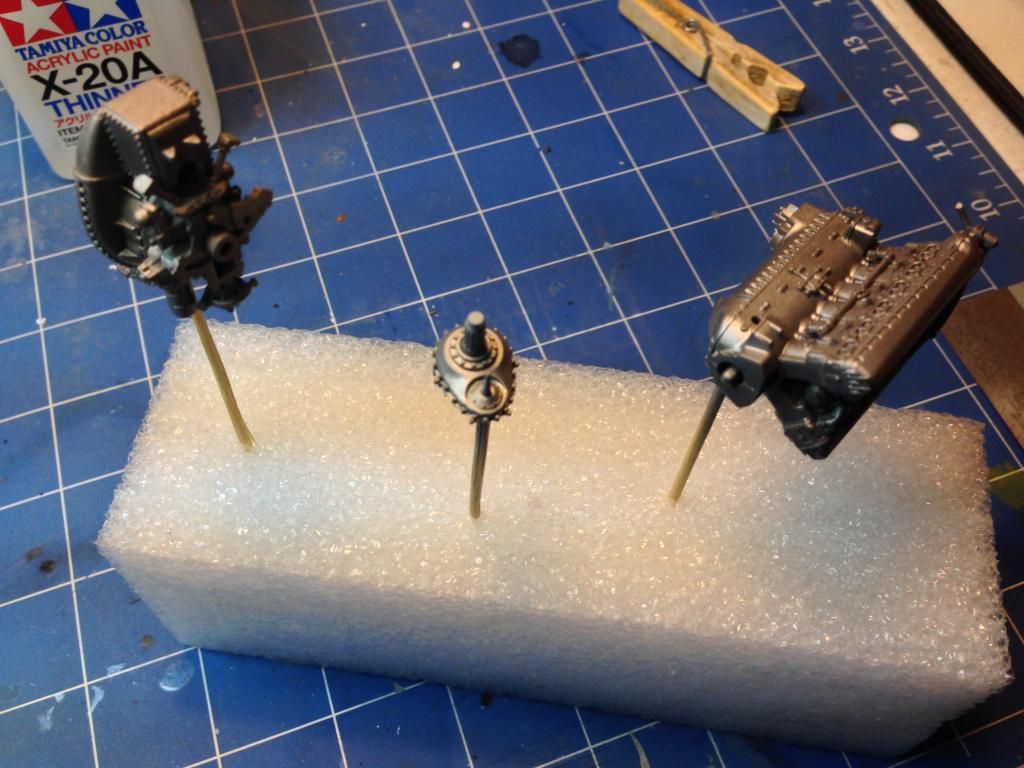
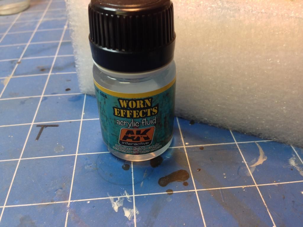
I used AK Interactive's worn effects to create some chipping effects on the engine.
In the next update the engine will be completed and work will commence on the cockpit.
On to part 3.