Welcome back. In this update I work on the rear of the engine, start work on the wings, sort out the radiator and fix a large gap in the wheel wells.
Power Egg
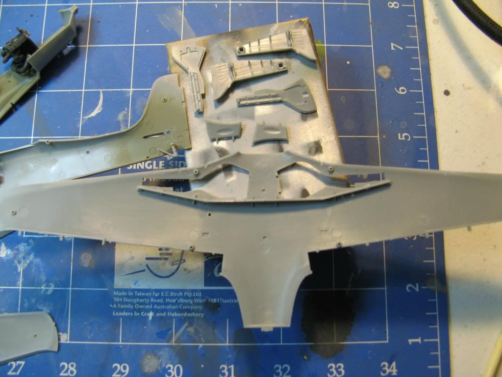
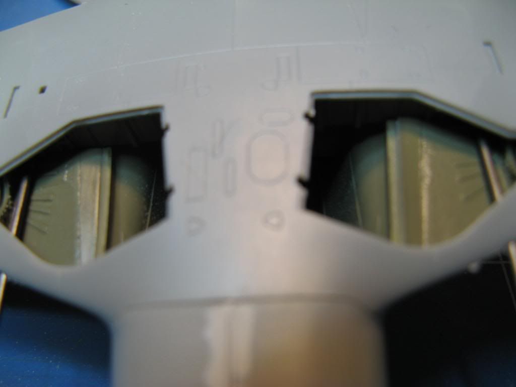
In the Ta-152 and in the Fw 190D from which it is derived the rear of the engine can be seen through the wheel wells. Hobby Boss have allowed for this in the form of the rear part of a DB603E engine. This is quite details as can be seen from the number of parts required to assemble it.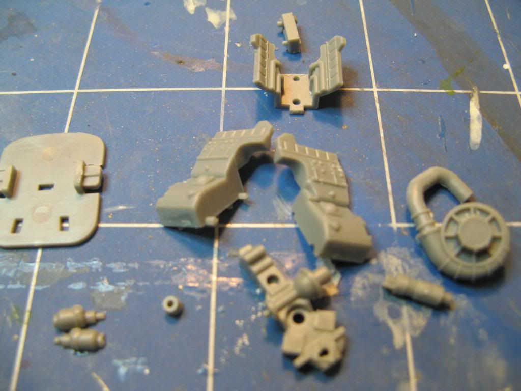
It does assemble into a rather nice representation of the back part of the engine. Pity there's no representation of the engine bearers though.
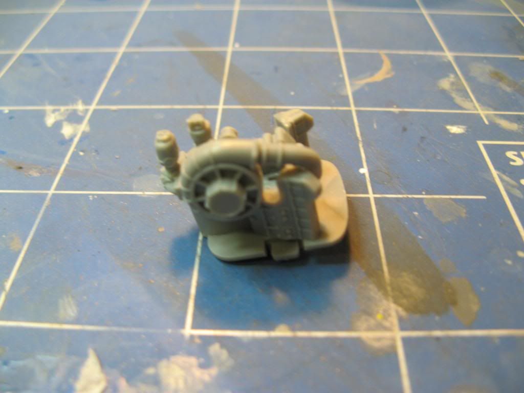
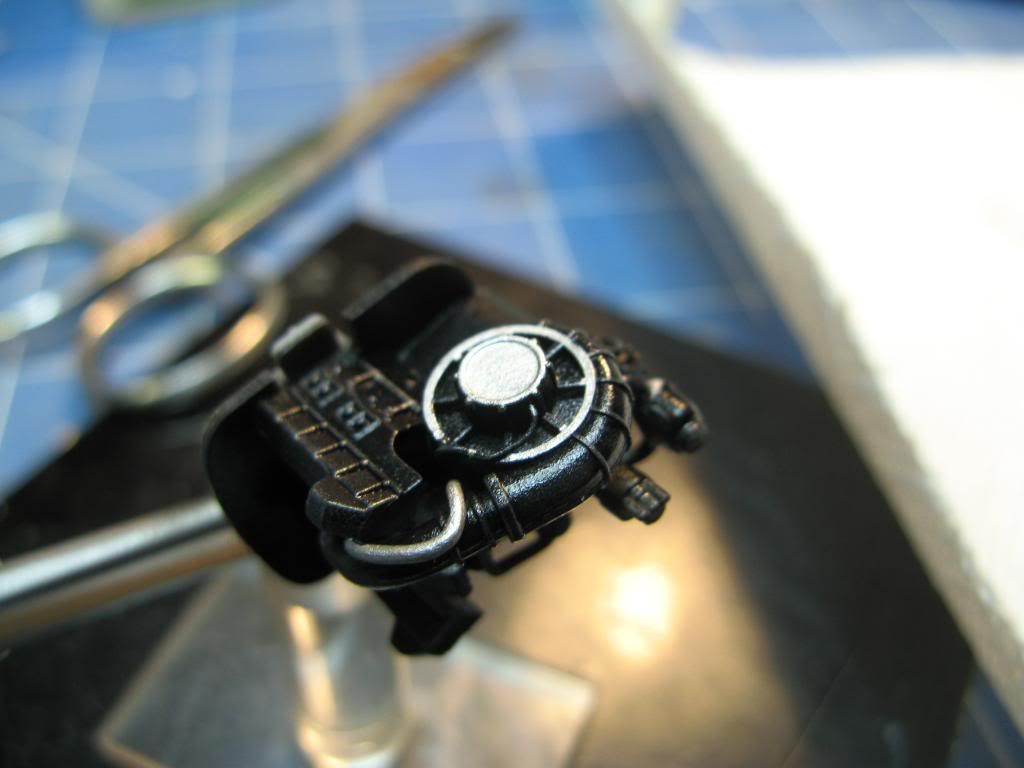
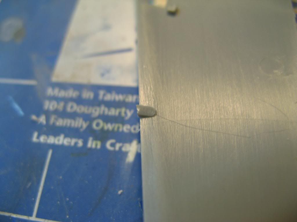
I did add a bit more detail using some lead wire before painting it.
Winging it
Assembly of the wings commences with the main spar which sits at the rear of the wheel wells. This part had six ejection pin marks which needed to be taken care of. I've coloured them in with a black marker pen to make them easier to see and to to indicate when they have been sanded out.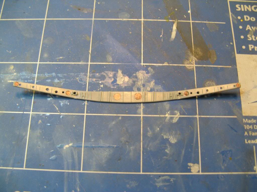
The lower wing section is moulded with gates that sit above the gluing surface. Care is needed to remove these without making a dip in the plastic. There was also a fair amount of flash on the leading edge which needed sanding off.
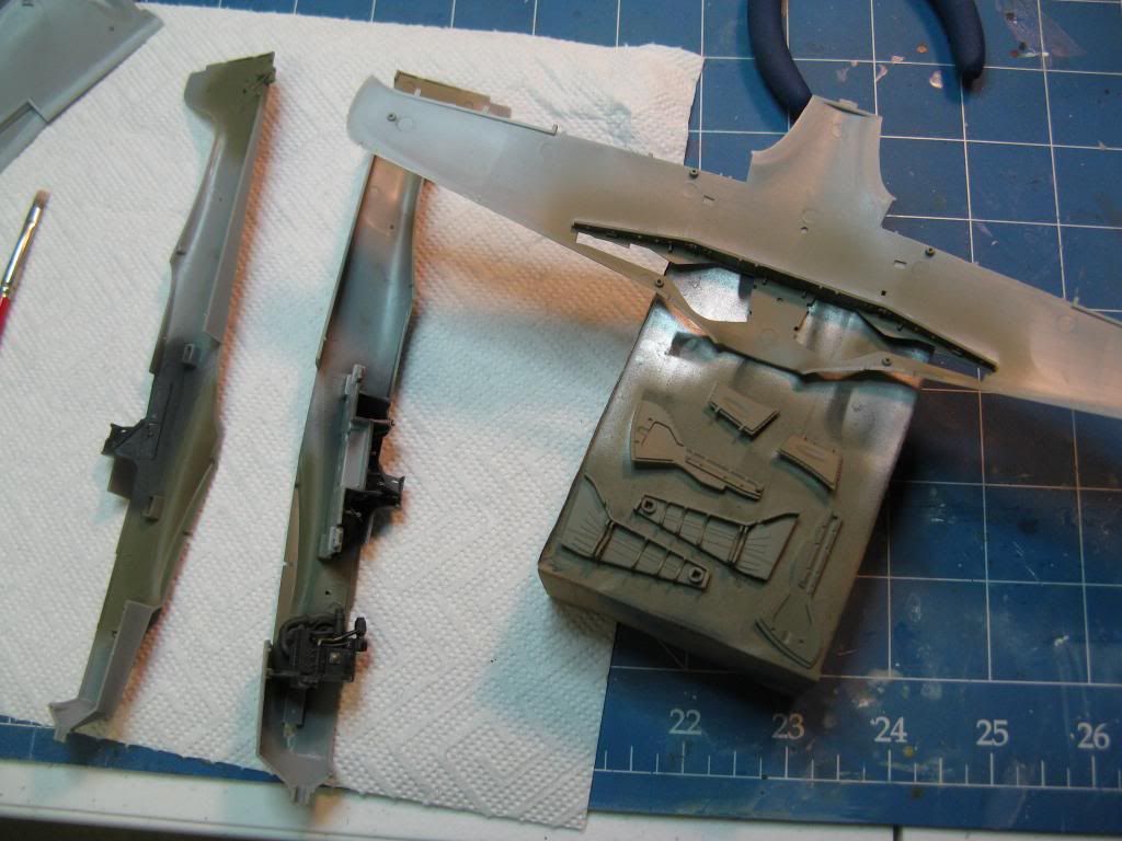
Given the wheel wells were to be painted RLM 02 grey I took the opportunity to prepare the insides of the gear doors too. Also I removed the bottom section of the tail wheel. Remember I have posed the rudder pedals off centre so I am going to have to reattach the tail wheel off centre as well.
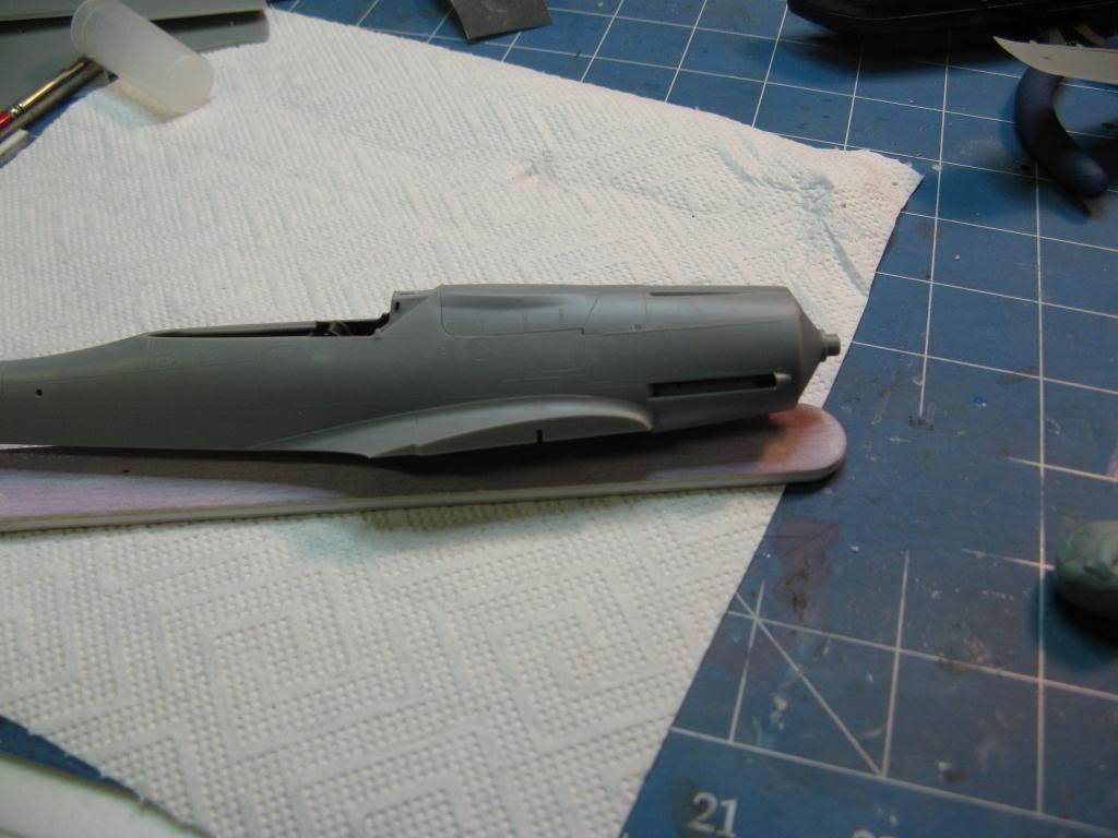
Don't Blow a Fuse
After painting the internals the fuselage was glued together. The fit was pretty good but there was some pressure needed on the instrument shroud which I tacked with super glue before gluing the rest.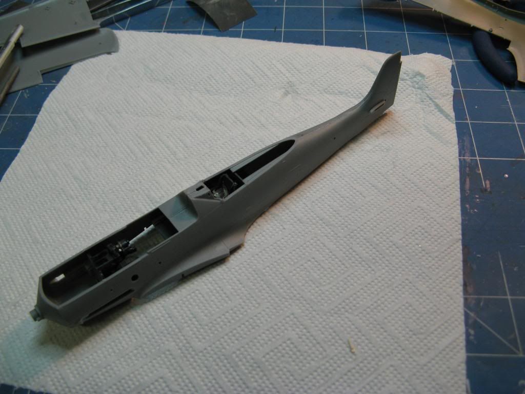
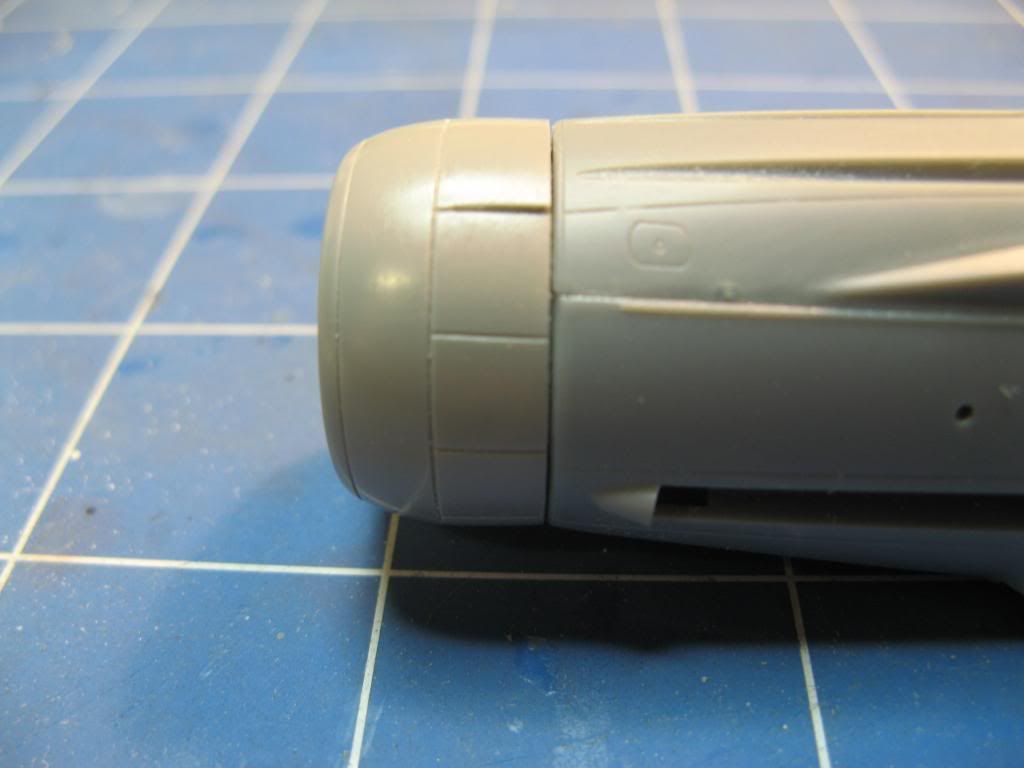
The cowl was then glued in place. Hobby Boss give you two cowls - one has a large hump on the left hand side and the other a smaller hump. This is because the supercharger of the production, C-1, model was larger as it was to use the DB603LA engine. For a this pre-production, C-0, model the cowling with the smaller hump is correct since the DB603E was used. The fit was pretty good.
Amputation
I mentioned in an earlier part that the Hobby Boss kit has the wrong radiator arrangement. This is corrected with a replacement from Quickboost. Here the patient is being prepared for surgery. The tub of water is for sanding the resin replacement. It keeps the dust down if you sand the resin wet.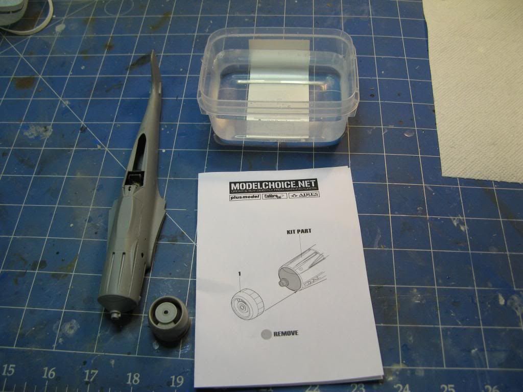
I first cut off the nose of the kit where the radiator assembly attaches. This was done with a razor saw and carefully sanded square. Then I used a razor saw to remove the casting block from the resin replacement and very carefully sanded it square using coarse wet and dry sand paper and plenty of water. Once dried the new resin radiator assembly was glued onto the fuselage. I am happy with the fit - enough of a gap to give the impression that the radiator cooling flaps can move.
The Grand Canyon Appears
When I test fit the lower wing to the fuselage with the wheel wells in place I noticed the first major issue with the fit of this kit. There is a massive gap between the wheel well and the wing mating surface on the fuselage. Check out the amount of daylight you can see!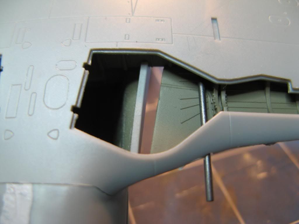
This called for extreme corrective action. First plasticard sheet was used to extend the length of the wheel well. I made a bit of a mess with the glue but I can clean that up later.

Once the glue had dried this sheet was then carefully trimmed to fit and a lip was glued onto the forward section. The wheel wells were then dry fit and with a black marker were used to draw a notch on the fuselage wing mating surface. This notch was then carefully cut out with a scriber and a sharp knife.
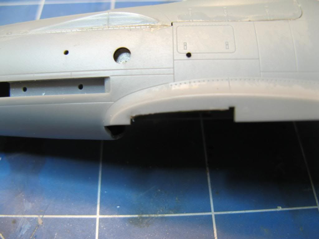
The wheel wells and inside the fuselage where they will mate was give a quick spray with RLM 02 grey and, hey presto, the gap has been taken care of.
That's all for this update. In the next update I'll tackle the propeller and get the main assembly completed.
On to part 4.